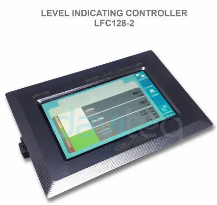
![]() Level Indicating
Level Indicating
Controller LFC128-2
USER GUIDE FOR LEVEL INDICATING CONTROLLER LFC128-2
LFC128-2-MN-EN-01 JUN-2020
LFC128-2 고급 레벨 디스플레이 컨트롤러
이 문서는 다음 제품에 적용됩니다.
| 제품유형 | LFC128-2 | 하드웨어 버전 | 1.0 | FW 버전 | 1.1 |
| 품목 코드 | LFC128-2 | Level Indicating Controller, 4AI/DI, 4DI, 4xRelay, 1xPulse Output, 2 x RS485/ModbusRTU-Slave Communication | |||
기능 변경 로그
| 하드웨어 버전 | FW 버전 | 출시일 | 기능 변화 |
| 1.0 | 1.1 | JUN-2020 | |
소개
LFC128-2 is an advanced level display controller. The product integrates Modbus RTU interface to help PLC / SCADA / BMS and any IoT port can connect to monitor. LFC128-2 has a simple yet powerful design with 4 AI / DI, 4 DI, 4 Relays, 1 Pulse pulse output, 2 RS485 Slave ModbusRTU allowing them to connect with multiple devices easily. With advanced technology that provides high stability and reliability, many functions, easy installation with touch screen and friendly interface helps visually monitor level.
사양
| 디지털 입력 | 04 x Ports, opto-coupler, 4.7 kohms input resisrtance, 5000V rms isolation, Logic 0 (0-1VDC), Logic 1 (5-24VDC), Functions: logic status 0/1 or Pulse counting (32 bit counter with max 4kHz pulse) |
| 아날로그 입력 | 04 x Ports, select between 0-10VDC input or 0-20mA input, 12 bit Resolution, can be configured as Digital input by DIP switch (max 10VDC input) The AI1 port is a 0-10 VDC / 4-20 mA level sensor connection port |
| 릴레이 출력 | 04 x Ports, electro-mechanical Relays, SPDT, contact rating 24VDC/2A or 250VAC/5A, LED indicators |
| 펄스 출력 | 01 x Ports, open-collector, opto-isolation, max 10mA and 80VDC, On/off control, Pulser (max 2.5Khz, max 65535 Pulses) or PWM (max 2.5Khz) |
| 의사소통 | 02 x ModbusRTU-Slave, RS485, speed 9600 or 19200, LED indicator |
| 리셋 버튼 | For resetting 02 x RS485 Slave port to default setting (9600, None parity, 8 bit) |
| 화면 유형 | 터치 스크린 |
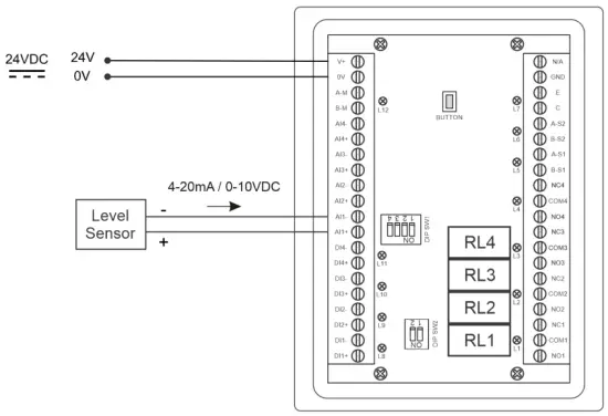
| 전원 공급 | 9..36VDC |
| 소비 | 200mA @ 24VDC supply |
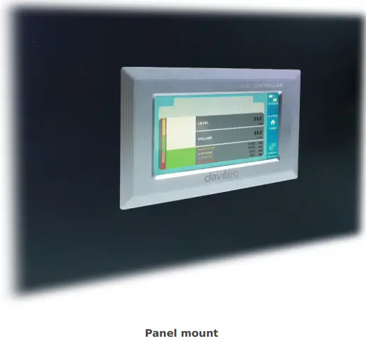
| 장착 유형 | 패널 마운트 |
| 터미널 블록 | pitch 5.0mm, rating 300VAC, wire size 12-24AWG |
| 작동 온도 / 습도 | 0..60 degC / 95%RH non-condensing |
| 차원 | H93xW138xD45 |
| 순중량 | 390그램 |
제품 사진


작동 원리

5.1 Modbus 통신

02 x RS485/ModbusRTU-Slave
프로토콜 : 모드버스 RTU
주소: 1 – 247, 0 is the Broadcast address
전송 속도: 9600, 19200
패리티 : 없음, 홀수, 짝수
- Status indicator LED:
- Led on: modbus communication OK
- Led blinking: received data but modbus communication incorrect, due to wrong Modbus configuration: address, baudrate
- Led off: LFC128-2 received no data, check the connection
멤맵 등록자
READ uses command 03, WRITE uses command 16
기본 구성:
- 주소 : 1
- Baudrate slave 1: 9600
- Parity slave 1: none
- Baudrate slave 2: 9600
- Parity slave 2: none
| Modbus 레지스터 | Hex adr | # of registers |
설명 | 범위 | 기본 | 체재 | 재산 | 논평 |
| 0 | 0 | 2 | 장치 정보 | LFC1 | 끈 | 읽다 | ||
| 8 | 8 | 1 | DI1 DI2: digital status | 0-1 | 단위8 | 읽다 | H_byte: DI1 L_byte: DI2 | |
| 9 | 9 | 1 | DI3 DI4: digital status | 0-1 | 단위8 | 읽다 | H_byte: DI3 L_byte: DI4 | |
| 10 | A | 1 | AI1 AI2: digital status | 0-1 | 단위8 | 읽다 | H_byte: AI1 L_byte: AI2 | |
| 11 | B | 1 | AI3 AI4: digital status | 0-1 | 단위8 | 읽다 | H_byte: AI3 L_byte: AI4 | |
| 12 | C | 1 | AI1: analog value | 단위16 | 읽다 | |||
| 13 | D | 1 | AI2: analog value | 단위16 | 읽다 | |||
| 14 | E | 1 | AI3: analog value | 단위16 | 읽다 | |||
| 15 | F | 1 | AI4: analog value | 단위16 | 읽다 | |||
| 16 | 10 | 2 | AI1: scaled value | 뜨다 | 읽다 | |||
| 18 | 12 | 2 | AI2: scaled value | 뜨다 | 읽다 | |||
| 20 | 14 | 2 | AI3: scaled value | 뜨다 | 읽다 | |||
| 22 | 16 | 2 | AI4: scaled value | 뜨다 | 읽다 | |||
| 24 | 18 | 1 | 릴레이 1 | 0-1 | 단위16 | 읽다 | ||
| 25 | 19 | 1 | 릴레이 2 | 0-1 | 단위16 | 읽다 | ||
| 26 | 1A | 1 | 릴레이 3 | 0-1 | 단위16 | 읽다 | ||
| 27 | 1B | 1 | 릴레이 4 | 0-1 | 단위16 | 읽다 | ||
| 28 | 1C | 1 | open collector ctrl | 0-3 | 단위16 | 읽기/쓰기 | 0: off 1: on 2: pwm, pulse continuously 3: pulse, when enough pulse number, ctrl = 0 | |
| 30 | 1E | 2 | counter DI1 | 단위32 | 읽기/쓰기 | counter writable, erasable | ||
| 32 | 20 | 2 | counter DI2 | 단위32 | 읽기/쓰기 | counter writable, erasable | ||
| 34 | 22 | 2 | counter DI3 | 단위32 | 읽기/쓰기 | counter writable, erasable | ||
| 36 | 24 | 2 | counter DI4 | 단위32 | 읽기/쓰기 | counter writable, erasable | ||
| 38 | 26 | 2 | counter AI1 | 단위32 | 읽기/쓰기 | counter writable, erasable, max frequency 10Hz | ||
| 40 | 28 | 2 | counter AI2 | 단위32 | 읽기/쓰기 | counter writable, erasable, max frequency 10Hz | ||
| 42 | 2A | 2 | counter AI3 | 단위32 | 읽기/쓰기 | counter writable, erasable, max frequency 10Hz | ||
| 44 | 2C | 2 | counter AI4 | 단위32 | 읽기/쓰기 | counter writable, erasable, max frequency 10Hz | ||
| 46 | 2E | 2 | DI1: time on | 단위32 | 읽기/쓰기 | 비서 | ||
| 48 | 30 | 2 | DI2: time on | 단위32 | 읽기/쓰기 | 비서 | ||
| 50 | 32 | 2 | DI3: time on | 단위32 | 읽기/쓰기 | 비서 | ||
| 52 | 34 | 2 | DI4: time on | 단위32 | 읽기/쓰기 | 비서 | ||
| 54 | 36 | 2 | AI1: time on | 단위32 | 읽기/쓰기 | 비서 | ||
| 56 | 38 | 2 | AI2: time on | 단위32 | 읽기/쓰기 | 비서 | ||
| 58 | 3A | 2 | AI3: time on | 단위32 | 읽기/쓰기 | 비서 | ||
| 60 | 3C | 2 | AI4: time on | 단위32 | 읽기/쓰기 | 비서 | ||
| 62 | 3E | 2 | DI1: time off | 단위32 | 읽기/쓰기 | 비서 | ||
| 64 | 40 | 2 | DI2: time off | 단위32 | 읽기/쓰기 | 비서 | ||
| 66 | 42 | 2 | DI3: time off | 단위32 | 읽기/쓰기 | 비서 | ||
| 68 | 44 | 2 | DI4: time off | 단위32 | 읽기/쓰기 | 비서 | ||
| 70 | 46 | 2 | AI1: time off | 단위32 | 읽기/쓰기 | 비서 | ||
| 72 | 48 | 2 | AI2: time off | 단위32 | 읽기/쓰기 | 비서 | ||
| 74 | 4A | 2 | AI3: time off | 단위32 | 읽기/쓰기 | 비서 | ||
| 76 | 4C | 2 | AI4: time off | 단위32 | 읽기/쓰기 | 비서 | ||
| 128 | 80 | 2 | counter DI1 | 단위32 | 읽다 | counter cannot write, erase | ||
| 130 | 82 | 2 | counter DI2 | 단위32 | 읽다 | counter cannot write, erase | ||
| 132 | 84 | 2 | counter DI3 | 단위32 | 읽다 | counter cannot write, erase | ||
| 134 | 86 | 2 | counter DI4 | 단위32 | 읽다 | counter cannot write, erase | ||
| 136 | 88 | 2 | counter AI1 | 단위32 | 읽다 | counter cannot write, erase; max frequency 10Hz | ||
| 138 | 8A | 2 | counter AI2 | 단위32 | 읽다 | counter cannot write, erase; max frequency 10Hz | ||
| 140 | 8C | 2 | counter AI3 | 단위32 | 읽다 | counter cannot write, erase; max frequency 10Hz | ||
| 142 | 8E | 2 | counter AI4 | 단위32 | 읽다 | counter cannot write, erase; max frequency 10Hz | ||
| 256 | 100 | 1 | modbus address slave | 1-247 | 1 | 단위16 | 읽기/쓰기 |
|
| 257 | 101 | 1 | modbus baudrate slave 1 | 0-1 | 0 | 단위16 | 읽기/쓰기 |
0:9600, 1:19200 |
| 258 | 102 | 1 | modbus parity slave 1 | 0-2 | 0 | 단위16 | 읽기/쓰기 |
0: 없음, 1: 홀수, 2: 짝수 |
5.2 재설정 버튼
When holding the reset button for 4 seconds, LFC 128-2 will reset the default configuration to 02 x RS485 / Modbus
RTU-Slave.
Default Modbus RTU Configuration:
- 주소 : 1
- 통신 속도: 9600
- 패리티: 없음
5.3 디지털 입력

사양:
- 04 channels DI, isolated
- Input Resistance: 4.7 kΏ
- 격리 볼륨tag전자: 5000Vrms
- Logic level 0: 0-1V
- Logic level 1: 5-24V
- 기능:
- Read logic 0/1
- 펄스 카운터
5.3.1 Read the logical state 0/1
Logic value in Modbus Memory Map: 0-1
Registers to store logic values in the Modbus Memory Map:
- DI1__DI2: digital status: stores the logical state of channel 1 and channel 2.
H_byte: DI1
L_byte: DI2 - DI3__DI4: digital status: store the logical state of channel 3 and channel 4.
H_byte: DI3
L_byte: DI4
5.3.2 Pulse Counter
Counter value in Modbus Memory Map, when adding the number exceeds the threshold, it will automatically return: 0 4294967295 (32bits)
The register that stores Counter value in the Modbus Memory Map cannot be erased:
- Counter DI1: stores the logic state of channel 1
- Counter DI2: stores the logic state of channel 2
- Counter DI3: store the logic state of channel 3
- Counter DI4: stores the logic state of channel 4
The register that stores Counter value in the Modbus Memory Map cannot be erased: - None reset counter DI1: stores the logic state of channel 1
- None reset counter DI2: stores the logic state of channel 2
- None reset counter DI3: stores the logic state of channel 3
- None reset counter DI4: stores the logic state of channel 4
Pulse Counter Mode:
Low-speed pulse count less than 10Hz with filter, anti-jamming:
- Set register “counter DI1: filter time” = 500-2000: Channel 1 counts pulses less than 10Hz
- Set register “counter DI2: filter time” = 500-2000: Channel 2 counts pulses less than 10Hz
- Set register “counter DI3: filter time” = 500-2000: Channel 3 counts pulses less than 10Hz
- Set register “counter DI4: filter time” = 500-2000: Channel 4 counts pulses less than 10Hz
- High-speed pulse count with max 2KHz frequency without filter:
- Set register “counter DI1: filter time” = 1: channel 1 counts pulses with Fmax = 2kHz
- Set register “counter DI2: filter time” = 1: channel 2 counts pulses with Fmax = 2kHz
- Set register “counter DI3: filter time” = 1: channel 3 counts pulses with Fmax = 2kHz
- Set register “counter DI4: filter time” = 1: channel 4 counts pulses with Fmax = 2kHz
5.4 아날로그 입력
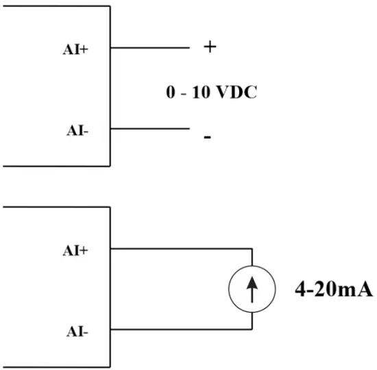
04 AI channels, no isolation (AI1 is a 4-20mA / 0-5 VDC / 0-10 VDC level sensor input )
Use DIP SW to configure Analog input: 0-10V, 0-20mA
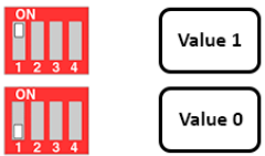
| 값 | Type of AI |
| 0 | 0-10V(전기) |
| 1 | 0~20mA |
입력 유형:
- 측정 볼륨tag전자: 0-10V
- Measure current: 0-20mA
- The configuration for AI reads the same logical state as DI, but it is not isolated with a pulse range of 0-24V
입력 임피던스:
- 측정 볼륨tage: 320 kΏ
- Measure the current: 499 Ώ
5.4.1 Read the Analog value
해상도 12비트
Non-Linearity: 0.1%
Analog value in Modbus Memory Map: 0-3900
Analog value register in the Modbus Memory Map:
- AI1 analog value: store the Analog value of channel 1
- AI2 analog value: stores the Analog value of channel 2
- AI3 analog value: store the Analog value of channel 3
- AI4 analog value: store the Analog value of channel 4
5.4.2 AI configuration works as DI
격리 없음
AI Configure AI to read the same logic state as DI with pulse amplitude from 0-24V
There are 2 counter threshold AIx: logic threshold 0 and counter AIx: threshold logic 1 in the modbus table: 0-4095
- Analog Analog value of AI <counter AIx: threshold logic 0: is considered Logic 0 status of AI
- Analog Analog value of AI> counter AIx: threshold logic 1: is considered to be Logic 1 state of AI
- Counter AIx: threshold logic 0 = <Analog value of AI <= counter AIx: threshold logic 1: is considered to be the constant logic state
Logic Logical status value of AI in Modbus Memory Map table: 0-1
The register stores logical values in Modbus Memory Map:
- AI1___AI2: digital status: stores the logical state of channel 1 and channel 2.
H_byte: AI1
L_byte: AI2 - AI3___AI4: digital status: stores the logical state of channel 1 and channel 2.
H_byte: AI3
L_byte: AI4
5.4.3 Pulse Counter AI max 10Hz
Counter value in Modbus Memory Map, when adding the number beyond the threshold, it will automatically return: 0 4294967295 (32bits)
The register that stores Counter value in the Modbus Memory Map cannot be erased:
- Counter AI1: stores the logic state of channel 1
- Counter AI2: save logic state of channel 2
- Counter AI3: save logic state of channel 3
- Counter AI4: save logic state of channel 4
The register that stores Counter value in the Modbus Memory Map cannot be erased: - None reset counter AI1: stores the logic state of channel 1
- None reset counter AI2: stores the logic state of channel 2
- None reset counter AI3: stores the logic state of channel 3
- None reset counter AI4: save logic state of channel 4
5.5 릴레이
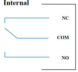
04 channel Relay SPDT NO / NC
Contact rating: 2A / 24VDC, 0.5A / 220VAC
There are status LEDs:
- Led on: Close Contact
- Led off: Open Contact
| Default Relay Register | Status of relays when resetting power supplies |
| 3 | Operate according to the Alarm configuration |
알람 구성:
- HIHI : Relay 4 On
- HI : Relay 3 On
- LO : Relay 2 On
- LOLO: Relay 1 On
5.6 펄스 출력

01 isolated open-collector channel
Opto-coupler: Source current Imax = 10mA, Vceo = 80V
기능: On / Off, pulse generator, PWM
5.6.1 On/Off Function
Set the Open-collector register in the Modbus Memory Map table:
- Set Open-collector register: 1 => Pulse Output ON
- Set Open-collector register: 0 => Pulse Output OFF
5.6.2 Pulse generator
Pulse output transmits a maximum of 65535 pulses, with Fmax 2.5kHz
Configure the following registers in the Modbus Memory Map table:
- Set register “open collector: pulse number”: 0-65535 => Pulse Number = 65535: broadcast 65535 pulses
- Set register “open collector: time cycle”: (0-65535) x0.1ms => Time Cycle = 4: Fmax 2.5kHz
- Set register “open collector: time on”: (0-65535) x0.1ms => Time On: is the logic time 1 of the pulse
- Set the register “open collector ctrl” = 3 => configure the Pulse Output to generate a pulse and start to pulse, generate a sufficient number of pulses in the “open collector: pulse number” register => stop pulse generator and register ” open collector ctrl ”= 0
5.6.3PWM
Max frequency 2.5kHz
Configure the following registers in the Modbus Memory Map table:
- Set the register “open collector ctrl” = 2 => configure Pulse Output PWM function
- Set register “open collector: time cycle”: (0-65535) x0.1ms => Time Cycle = 4: Fmax 2.5kHz
- Set register “open collector: time on”: (0-65535) x0.1ms => Time On: is the logic time 1 of the pulse
설치
6.1 설치 방법
 6.2 Wiring with Level Sensor

구성
7.1 홈 화면

화면: Switch to 2nd screen with more detailed information
경보 : Show Level Alert
집: 홈 화면으로 돌아가기
구성 (Default Password: a): Go to Setting Screen
7.2 Setting screen (Default Password: a)
7.2.1 화면 1
![daviteq LFC128 2 Advanced Level Display Controller - Home Screen 1] '](https://manuals.plus/wp-content/uploads/2025/08/daviteq-LFC128-2-Advanced-Level-Display-Controller-Home-Screen-1-550x305.png)
ADC : Raw signal value of channel AI1
Level (Unit): The level corresponds to the ADC signal after configuration
Decimal Places Level:Decimal number of digits after the dot of Level 0-3 (00000, 1111.1, 222.22, 33.333)
Unit level: level units, 0-3 (0: mm, 1: cm, 2: m, 3: inch)
1에서: Enter the ADC value after putting 4 mA / 0 VDC into AI1 for calibration at 0 level
1 크기 조정: The level value displayed corresponds to the value entered in In 1 (usually 0)
2에서: Enter the ADC value after putting 20 mA / 10 VDC into AI1 for calibration at Full level
2 크기 조정: The level value displayed corresponds to the value entered in In 2
Span Level: Maximum value of Level (Span Level ≥ Scale 2)
Decimal Places Volume: Decimal number of digits after the dot of Volume 0-3 (00000, 1111.1, 222.22, 33.333)
Unit Volume: units of volume 0-3 (0: lit, 1: cm, 2: m3, 3:%)
7.2.2 화면 2

Level Hi Hi Set point (Unit): High High level of Alarm Level
Level Hi Hi Hys (Unit): High High level hysteresis of Alarm Level
Level Hi Set point (Unit): High level of Alarm Level
Level Hi Hys (Unit): High level hysteresis of Alarm Level
Level Lo Set point (Unit): Low level of Alarm Level
Level Lo Hys (Unit): Low level hysteresis of Alarm Level
Level Lo Lo Set point (Unit): Low Low level of Alarm Level
Level Lo Lo Hys (Unit): Low Low level hysteresis of Alarm Level
알람 모드 : 0: Level, 1: Volume
Span Volume(Unit): Maximum value of the volume
7.2.3 화면 3

Volume Hi Hi Set point (Unit): High High volume of Alarm Volume
Volume Hi Hi Hys (Unit): High High volume hysteresis of Alarm Volume
Volume Hi Set point (Unit): High volume of Alarm Volume
Volume Hi Hys (Unit): High volume hysteresis of Alarm Volume
Volume Lo Set point (Unit): Low volume of Alarm Volume
Volume Lo Hys (Unit): Low volume hysteresis of Alarm Volume
Volume Lo Lo Set point (Unit): Low Low volume of Alarm Volume
Volume Lo Lo Hys (Unit): Low Low volume hysteresis of Alarm Volume
Run Total: Run the total function. 0-1 (0: No 1: Yes)
7.2.4 화면 4

Filling (Unit): Total function: total put into tank
Consumption (Unit): Total function: total consumption of the tank
Decimal Places Total: Decimal number of parameters Filling, Consumption, NRT Filling, NRT Consumption on display page (not the setting page)
Delta Total (Unit): Hysteresis level of the total function
모드버스 주소: Modbus address of LFC128-2, 1-247
Modbus Baurate S1: 0-1 (0 : 9600 , 1 : 19200)
Modbus Parity S1: 0-2 (0: none, 1: odd, 2: even)
Modbus Baurate S2: 0-1 (0 : 9600 , 1 : 19200)
Modbus Parity S2: 0-2 (0: none, 1: odd, 2: even)
Num of Points: Number of points in the table to convert from level to volume, 1-166
7.2.5 화면 5

Point 1 Level (Level Unit): Level at Point 1
Point 1 Volume (Volume Unit): The corresponding volume at Point 1
Point 166 Level (Level Unit): Fuel level at Point 166
Point 166 Volume (Volume Unit): The corresponding volume at Point 166
7.2.6 화면 6

비밀번호: Password to enter the Setting page, 8 ASCII characters
Tank Name: Tank name displayed on the main screen
문제 해결
| 아니요. | 현상 | 이유 | 솔루션 |
| 1 | Modbus failed to communicate | Modbus LED Status: LED is off: received no data LED is blinking: the Modbus configuration is not the correct | Check the connection Check the Modbus configuration: Address, Baud Rate, Parity |
| 2 | Timeout Modbus | Noise appears on the line | Configure Baudrate 9600 and use a twisted pair cable with anti-jamming protection |
| 3 | 센서 연결 끊김 | Sensor and LFC128 lost connection | Checking connection Check sensor type (LFC128-2 only connects to 0-10VDC / 4- 20mA analog sensor type) Check the switch to see if it is turned on correctly Check that the sensor connector is correct AI1 |
| 4 | Linearization table error | Error of conversion table from level to volume | Check the configuration of the conversion table from level to volume |
지원 연락처
제조업체
Daviteq 기술 Inc
베트남 호치민시 빈탄구 안락구 남흥브엉 유적 11번가 2G.
Tel: +84-28-6268.2523/4 (ext.122)
이메일: info@daviteq.com
www.daviteq.com
문서 / 리소스
 |
daviteq LFC128-2 Advanced Level Display Controller [PDF 파일] 사용설명서 LFC128-2, LFC128-2 Advanced Level Display Controller, Advanced Level Display Controller, Level Display Controller, Display Controller |