1. 서론
This manual provides detailed instructions for the installation, operation, and maintenance of your Antec Flux Rear Mid-Tower ATX PC Case. Please read this manual thoroughly before beginning assembly to ensure correct setup and optimal performance.
안전 정보: Always disconnect power from all components before installation or maintenance. Handle components with care to prevent damage. Wear an anti-static wrist strap when handling sensitive electronic parts.
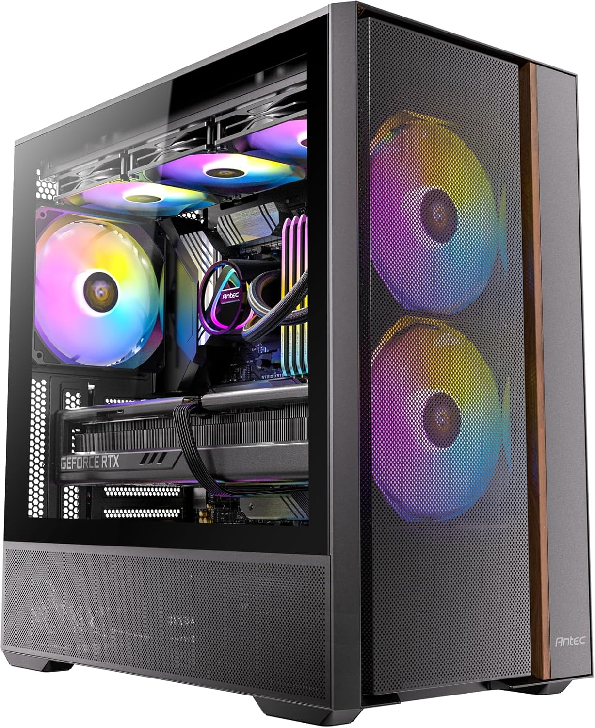
Image: The Antec Flux Rear Mid-Tower ATX PC Case, showcasing its tempered glass side panel, mesh front panel, and pre-installed RGB fans.
2. 패키지 내용
아래 나열된 모든 구성 요소가 패키지에 들어 있는지 확인하세요.
- Antec Flux Rear Mid-Tower ATX PC Case
- 2 x 140mm ARGB PWM Fans (Front, pre-installed)
- 2 x 120mm PWM Reverse Fans (PSU Shroud, pre-installed)
- 1 x 140mm ARGB PWM Fan (Rear, pre-installed)
- 부속품 상자 (나사, 케이블 타이, 사용 설명서)
- 13A PSU Extension Cable
- GPU 지원 브래킷

이미지: 폭발된 view illustrating the various components of the Antec Flux Rear PC case, including the chassis, panels, and fans.
3. 사양
| 특징 | 세부 사항 |
|---|---|
| 모델명 | Flux Rear |
| 케이스 유형 | 미드 타워 |
| 마더보드 호환성 | ATX, Micro-ATX, ITX (Supports Back-Connect Motherboards) |
| 치수(길이x너비x높이) | 18.11 x 18.11 x 9.45인치(460 x 460 x 240mm) |
| 품목 무게 | 18.03파운드(8.18kg) |
| 재료 | 합금강, 강화유리 |
| 사전 설치된 팬 | 2x 140mm ARGB PWM (Front), 2x 120mm PWM Reverse (PSU Shroud), 1x 140mm ARGB PWM (Rear) |
| 팬 지원(최대) | Front: 2x 140mm; Top: 2x 140mm or 3x 120mm; Rear: 1x 140mm or 1x 120mm; PSU Shroud: 2x 120mm |
| 라디에이터 지지대(최대) | 상단: 최대 360mm; 후면: 최대 120mm |
| CPU 쿨러 최대 높이 | 180mm (XNUMXmm) |
| GPU 최대 길이 | 400mm (XNUMXmm) |
| 전원 공급 장치 장착 | Front Mount (Max length without cable: 170mm) |
| 드라이브 베이 | 1개 3.5인치, 2개 2.5인치 |
| I/O 포트 | 2x USB 3.0, 1x USB-C 10Gbps, Headphone/Mic Combo Jack, Power Button, LED Control Button |
4. 설정 및 설치
4.1 사건 준비
The Antec Flux Rear case features a tool-free panel design for easy access during assembly.
- To remove the tempered glass side panel, gently pull it open from the rear hinge.
- The metal right side panel can be removed by sliding it backward and lifting.
- The front mesh panel can be detached by pulling it from the bottom edge.
- The top panel can be lifted off after removing any securing screws.

Image: Illustration of the tool-free panel design, demonstrating how to remove the top, left glass, left metal, and front panels for access.
4.2 마더 보드 설치
The case supports ATX, Micro-ATX, and ITX motherboards, including back-connect models.
- Ensure the correct standoffs are installed for your motherboard size.
- 마더보드를 섀시에 조심스럽게 넣고 스탠드오프와 I/O 쉴드 구멍에 맞춰 정렬하십시오.
- 제공된 나사로 마더보드를 고정합니다.
- For back-connect motherboards, route all necessary cables through the designated cutouts behind the motherboard tray.

이미지: 내부 view of the case demonstrating support for back-connect motherboards, with highlighted cable routing paths behind the motherboard tray.
4.3 전원 공급 장치 설치
The Antec Flux Rear features a front-mounted PSU chamber.
- Install your power supply unit (PSU) into the front chamber.
- Connect the included 13A extension cable to the PSU and route it to the rear power inlet.
- Ensure the extension cable is securely connected and routed to avoid interference.

이미지: A view of the front-mounted PSU chamber and the 13A extension cable, illustrating how the power supply is positioned and connected.

Image: Four distinct diagrams illustrating various methods for routing the power extension cable, depending on the power connector's position and desired cable path.
4.4 드라이브 설치(HDD/SSD)
The case provides dedicated mounting points for storage drives.
- Install 3.5" hard disk drives (HDDs) in the designated bay located at the rear of the case.
- Install 2.5" solid-state drives (SSDs) in the mounting locations behind the motherboard tray.
- Secure all drives with the provided screws.

Image: An internal diagram of the PC case, clearly marking the installation areas for the CPU, GPU, Motherboard, SSD, HDD, and Power Supply.
4.5 그래픽 카드 설치
Install your graphics card into the appropriate PCIe slot on your motherboard.
- 케이스 뒷면에서 필요한 PCIe 슬롯 커버를 제거합니다.
- Insert the graphics card firmly into the PCIe slot until it clicks into place.
- 그래픽 카드를 나사로 고정합니다.
- Utilize the built-in GPU support bracket to prevent sag for heavier graphics cards. Adjust the bracket to support the card's weight.

Image: A close-up illustration of the built-in GPU support bracket, demonstrating its function in preventing graphics card sag.
4.6 팬 및 라디에이터 설치
The case comes with five pre-installed PWM fans and offers extensive support for additional cooling.
- 맨 위: Supports up to 360mm radiators or 2x 140mm / 3x 120mm fans.
- 뒤쪽: Supports 1x 140mm or 1x 120mm fan, or a 120mm radiator (with thickness between 55-70mm).
- 앞쪽: Supports 2x 140mm fans.
- PSU 덮개: Supports 2x 120mm fans.
- When installing radiators, ensure proper clearance with other components.
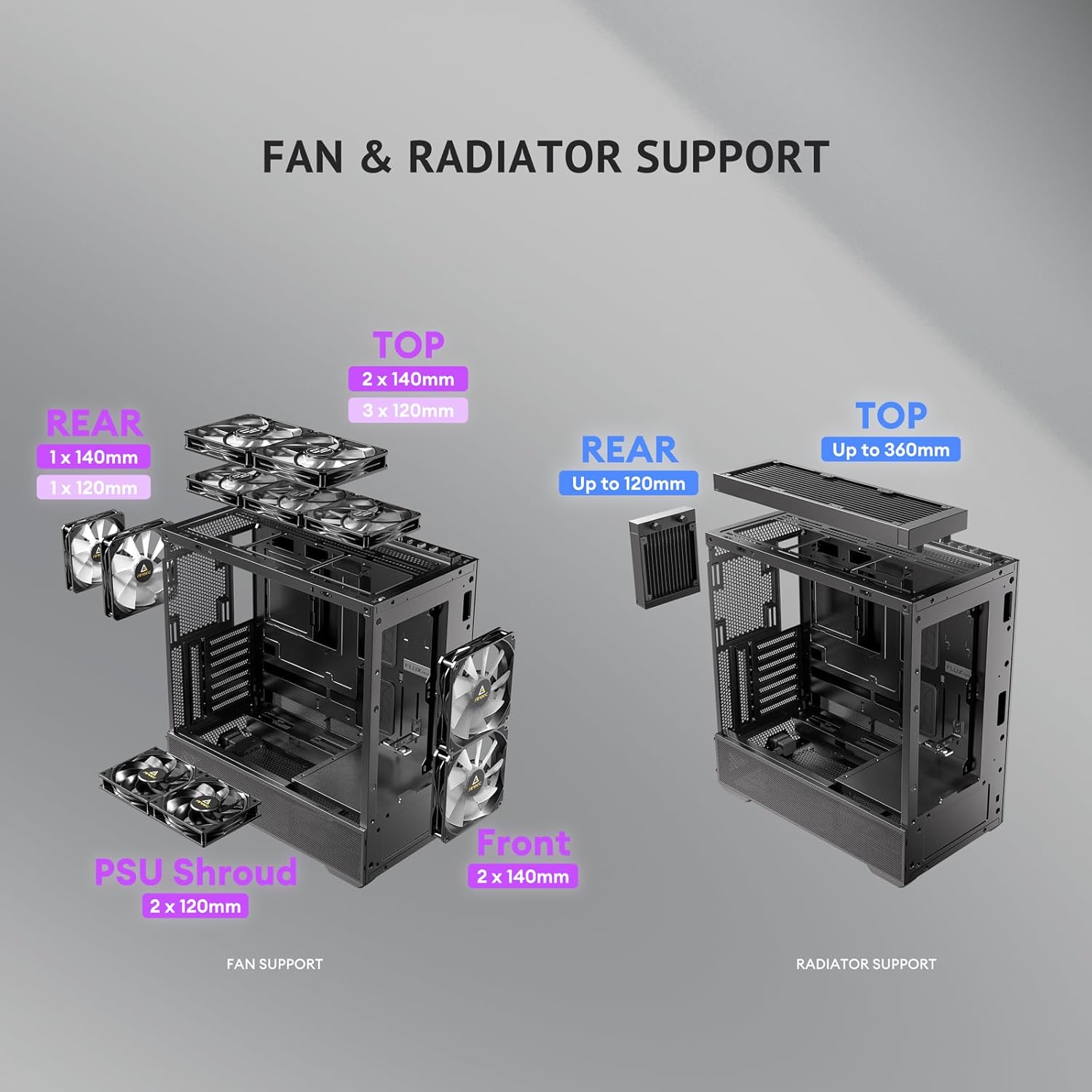
Image: A diagram illustrating the various fan and radiator mounting locations within the PC case, along with their supported sizes.

Image: An illustration detailing the installation process for a 360mm radiator and a rear fan in the top section of the PC case.
4.7 케이블 관리
The case offers 37mm of space behind the motherboard tray for cable management, equipped with grommets and Velcro straps.
- Route power and data cables through the grommets and tie-down points.
- Use the included Velcro straps to bundle and secure cables, ensuring a clean interior and unobstructed airflow.
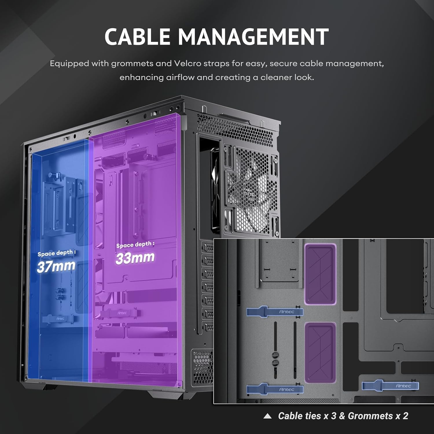
Image: A diagram illustrating the cable management features behind the motherboard tray, including space depth, cable ties, and grommets.
5. 운영
5.1 전원 켜기
After completing all installations and connections, ensure the power cable is securely plugged into the rear of the case and a power outlet. Press the power button located on the top I/O panel to start your system.
5.2 입출력 패널 기능
상단 I/O 패널은 필수 포트 및 제어 장치에 편리하게 접근할 수 있도록 설계되었습니다.
- 전원 버튼: 시스템을 켜거나 끕니다.
- USB 3.0 포트(x2): USB 3.0 장치를 연결하는 데 사용됩니다.
- USB-C 10Gbps Port: For connecting USB-C devices with high-speed data transfer.
- 헤드폰/마이크 콤보 잭: 오디오 입력/출력용.
- LED 버튼: Controls the lighting effects of the ARGB fans.

이미지: 클로즈업 view of the top I/O panel, detailing the power button, USB 3.0 ports, USB-C 10Gbps port, headphone/mic combo jack, and LED control button.
5.3 공기 흐름 및 냉각
The Antec Flux Rear case is designed with the F-LUX Platform for optimized airflow and cooling performance.
- F-LUX Platform: Features a front-mounted PSU chamber that creates an unobstructed airflow path at the bottom of the case, enhancing GPU cooling.
- Multi-directional Vent Design: Incorporates extensive air intakes at the bottom, power supply chamber, lower sides, top, and a large-area mesh front panel to create a dedicated airflow channel.
- 사전 설치된 팬: The five pre-installed PWM fans are strategically placed to facilitate efficient air movement throughout the case.

Image: A diagram illustrating the 'Flow Luxury' F-LUX Platform, showing the internal airflow paths designed to enhance GPU cooling.

Image: A diagram detailing the 'Flux Airflow' system, indicating the positions and directions of the pre-installed fans within the PC case.
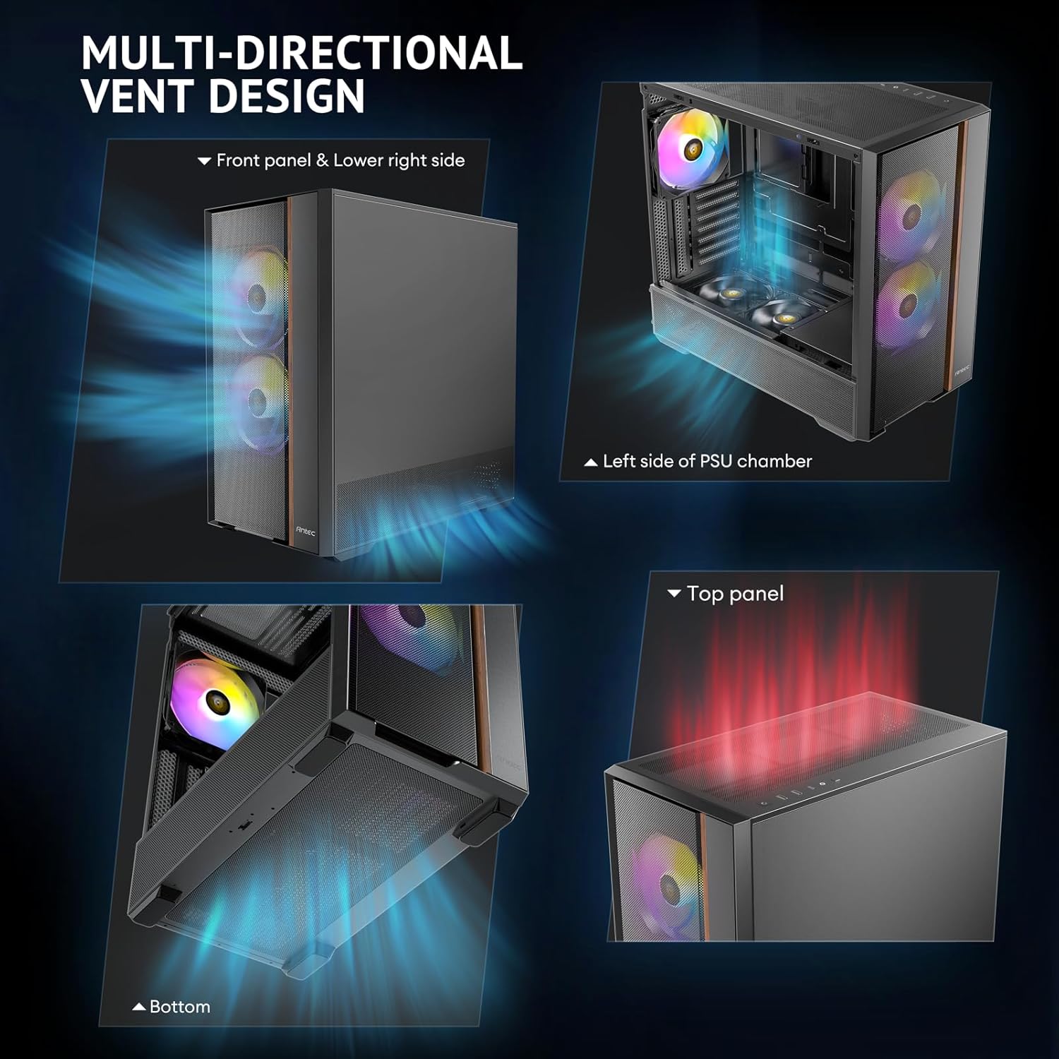
Image: Four separate images highlighting the multi-directional vent design, showing air intake points on the front panel, lower right side, left side of the PSU chamber, and the top panel.

Image: A diagram illustrating the optimized bottom air intake, specifically designed for efficient GPU cooling, with measurements for graphics card space and bottom clearance.
6. 유지관리
정기적인 유지관리는 PC 케이스의 최적의 성능과 수명을 보장하는 데 도움이 됩니다.
- 먼지 필터: 케이스 앞면, 윗면, 아랫면에 있는 먼지 필터를 주기적으로 분리하여 청소하십시오. 압축 공기나 부드러운 브러시를 사용하여 쌓인 먼지를 제거하세요.
- 외부 청소: 부드러운 d로 외부 표면을 닦으십시오.amp 천으로 닦으십시오. 마감재를 손상시킬 수 있는 연마성 세척제나 용제는 사용하지 마십시오.
- 내부 청소 : 시스템 전원을 끄고 플러그를 뽑은 후, 압축 공기를 사용하여 내부 부품과 팬의 먼지를 제거하십시오.
7. 문제 해결
PC 케이스에 문제가 발생하면 다음의 일반적인 문제 및 해결 방법을 참조하십시오.
- 시스템 전원이 켜지지 않음:
- Ensure the PSU is properly installed and connected to the 13A extension cable.
- Verify that the power button cable is correctly connected to the motherboard's front panel header.
- 전원 콘센트가 작동하는지 확인하세요.
- Fans Not Spinning or No RGB:
- 팬 전원 케이블이 마더보드 또는 팬 컨트롤러에 제대로 연결되어 있는지 확인하십시오.
- Ensure ARGB cables are connected to the motherboard's ARGB header or a compatible controller.
- Press the LED button on the I/O panel to cycle through lighting modes or ensure it's enabled.
- USB 포트가 작동하지 않음:
- Check if the USB 3.0 and USB-C cables from the front panel are correctly connected to the motherboard headers.
8. 보증 및 지원
Antec products are covered by a limited warranty. For specific warranty terms and conditions, please refer to the warranty card included with your product or visit the official Antec web대지.
For technical support, product inquiries, or assistance with troubleshooting, please contact Antec customer service through their official web사이트 또는 제품 설명서에 제공된 연락처 정보를 참조하세요.


