1. 서론
This manual provides essential information for the setup, operation, and maintenance of the Waveshare ESP32-P4 High-Performance Development Board. The ESP32-P4-Module-DEV-KIT-C is designed for multimedia and edge computing applications, featuring a 400MHz RISC-V dual-core processor, Wi-Fi 6, Bluetooth 5/BLE, and extensive peripheral support. This specific kit includes a 10-inch DSI Capacitive Touch Display and an RPi Camera (B).
The board offers comprehensive connectivity and rich human-machine interfaces, making it suitable for complex multimedia projects. It also incorporates advanced security features to ensure robust data protection.
2. 패키지 내용
Verify that all items listed below are present in your package. Refer to the image for visual confirmation of the components included in the ESP32-P4-Module-DEV-KIT-C.
- ESP32-P4-Module-DEV-KIT-C Development Board x1
- 10.1-DSI-TOUCH-A 10-inch DSI Capacitive Touch Display x1
- RPi 카메라(B) x1
- Speaker (8Ω 2W) x1
- 나사 팩 x1
- USB Type-A 듀얼 플러그 케이블 x1
- USB Type-A to Type-C cable x1
- DSI cable x1
- FFC 15핀 케이블 x1
- FFC 22PIN cable (2PCS) x1
- 2PIN cable x1
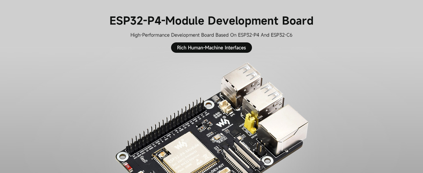
Figure 2.1: Contents of the ESP32-P4-Module-DEV-KIT-C package.
3. 제품 오버view
The Waveshare ESP32-P4 Development Board is a high-performance platform built around the ESP32-P4 and ESP32-C6 modules, offering robust capabilities for various embedded projects.
3.1 주요 특징
- 고성능 프로세서: Features a 400MHz RISC-V dual-core processor for enhanced performance.
- 메모리: Up to 32MB PSRAM and 16MB Nor Flash for ample storage and processing.
- 무선 연결 : Supports Wi-Fi 6 and Bluetooth 5/BLE for versatile communication.
- 풍부한 인터페이스: Includes MIPI-CSI (Camera), MIPI-DSI (Display), I2S, SPI, I2C, UART, USB 2.0 OTG, and more.
- Ethernet with PoE: Onboard RJ45 Ethernet with Power over Ethernet (PoE) functionality.
- GPIO 헤더: 40-pin GPIO header compatible with Raspberry Pi HATs.
- 보안: Secure Boot, Flash Encryption, cryptographic accelerators, and TRNG for data security.
- 멀티미디어 지원: Designed for multimedia applications with integrated image signal processor and H.264 encoder.

Figure 3.1: ESP32-P4-Module Development Board overview.
3.2 Integrated Modules
The board integrates the ESP32-P4-Module, which includes the ESP32-C6 for Wi-Fi 6 and Bluetooth 5/BLE connectivity, and 16MB Nor Flash.

Figure 3.2: ESP32-P4-Module for high performance.
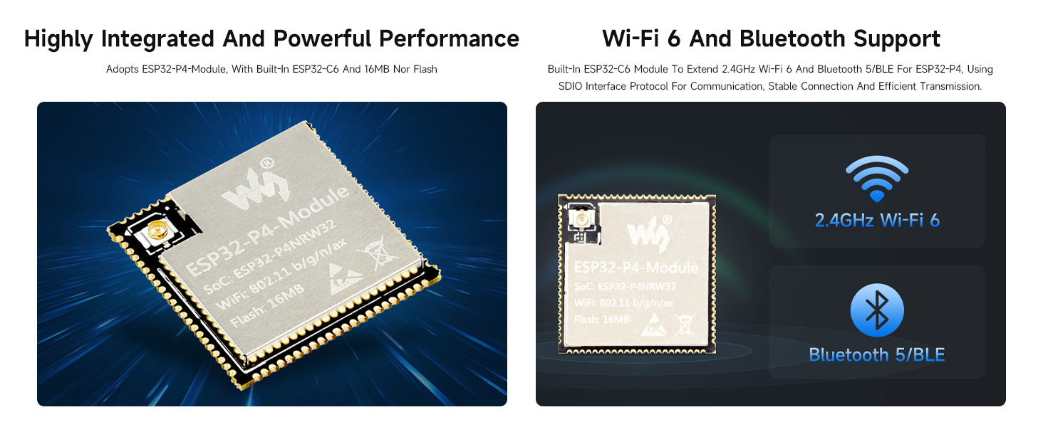
Figure 3.3: Wi-Fi 6 and Bluetooth 5/BLE support.
3.3 PoE 전원 공급 장치
The board includes a reserved PoE module header, allowing for power supply and network connection through a single Ethernet cable when connected to a compatible PoE module (not included).
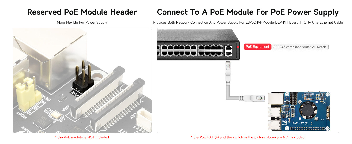
Figure 3.4: Reserved PoE module header.
4. 보드 레이아웃 및 핀 배치
Understanding the board's layout and pin definitions is crucial for proper connection and development.
4.1 탑승객 안내
The following diagram identifies key components and interfaces on the ESP32-P4-Module-DEV-KIT-C.

Figure 4.1: Labeled components of the ESP32-P4-Module-DEV-KIT-C.
4.2 Pin Definition and Outline Dimensions
The 40-pin GPIO header provides various power and data pins. Refer to the diagram for pin assignments and board dimensions.
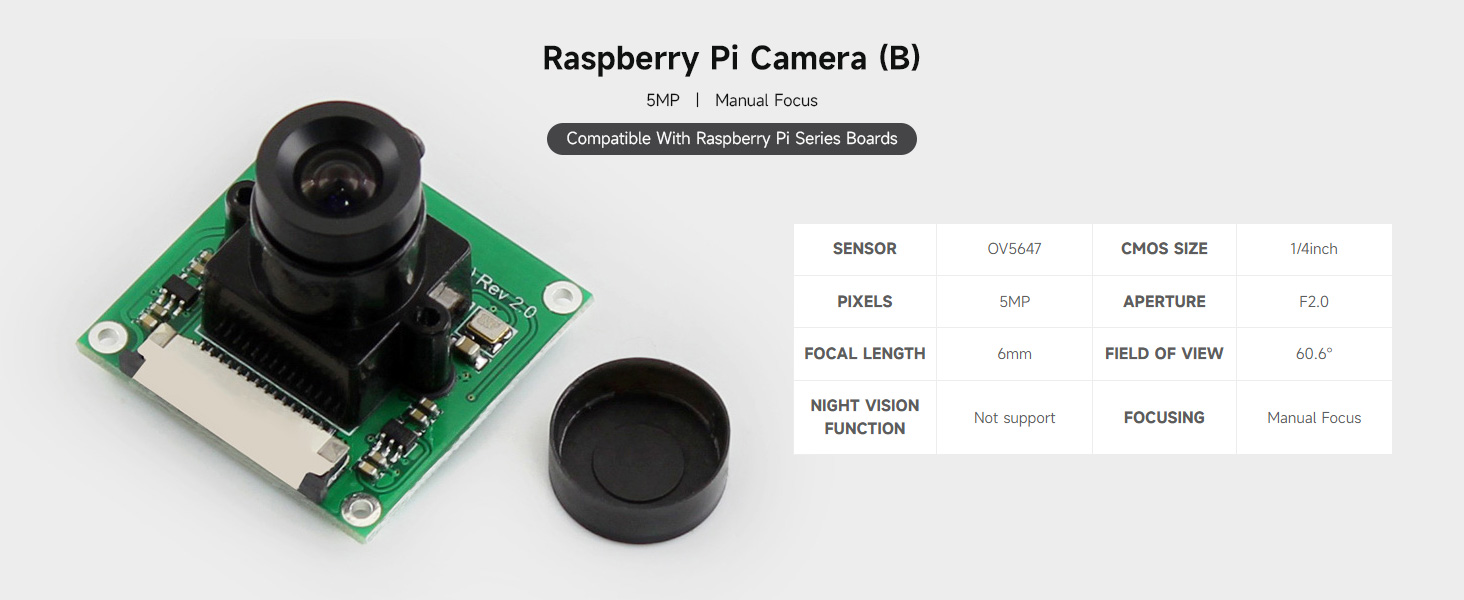
Figure 4.2: Pin definitions and outline dimensions.
5. 설정 및 연결
This section guides you through connecting the various components of your ESP32-P4 development kit.
5.1 Kit Selection Overview
The ESP32-P4-Module-DEV-KIT is available in several configurations. This manual focuses on the 'C' kit, which includes the 10-inch DSI LCD and RPi Camera (B).
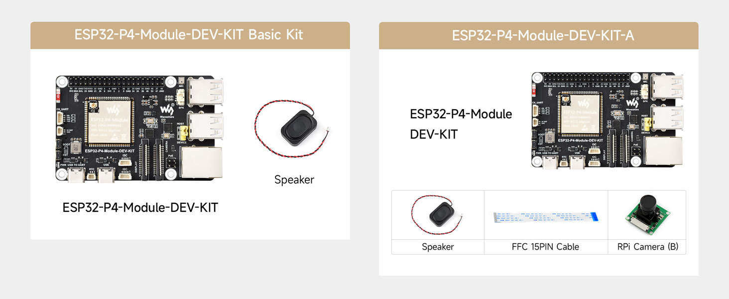
그림 5.1: 이상view of available kit configurations.
5.2 연결 예amp레
Follow these general steps for connecting the display and camera to the development board:
- Connect the DSI Display: Carefully connect the DSI cable from the 10.1-DSI-TOUCH-A display to the MIPI-DSI interface on the ESP32-P4 board. Ensure the cable is inserted correctly and secured.
- Connect the RPi Camera: Attach the RPi Camera (B) to the MIPI-CSI interface on the development board using the provided FFC cable.
- 전원 연결: Connect the USB Type-A to Type-C cable to the Type-C UART connector on the board for power and programming.
- 스피커 연결: Connect the 8Ω 2W speaker to the designated speaker header.

그림 5.2: 예ample connections for the development kit.
6. 사용 설명서
After connecting all components, you can begin operating your ESP32-P4 Development Board. The board typically runs a Linux operating system and supports various development environments.
- 전원 켜기: Connect the Type-C USB cable to a power source. The power supply indicator LED should illuminate.
- 소프트웨어 개발: 자세한 프로그래밍 가이드 및 예시는 다음을 참조하세요.amples, refer to the official Waveshare Wiki resources. This includes information on using ESP-IDF and potentially Arduino IDE for development.
- 다운로드 모드 진입 중: Press and hold the BOOT button, then press the RST Reset button to enter download mode for flashing firmware.
- USB OTG: The USB OTG 2.0 high-speed ports can be switched between host and device via a jumper for expanded USB functionalities.
It is recommended to consult the Waveshare Wiki for the latest software, drivers, and specific programming instructions relevant to the ESP32-P4 and ESP32-C6 modules.
7. 유지관리
Proper maintenance ensures the longevity and reliable operation of your ESP32-P4 Development Board.
- 손질: Always handle the board by its edges to avoid touching sensitive components. Use anti-static precautions when possible.
- 청소: 기판에 먼지와 이물질이 쌓이지 않도록 하십시오. 청소할 때는 부드럽고 마른 브러시나 압축 공기를 사용하십시오. 액체 세척제는 사용하지 마십시오.
- 저장: 도마는 직사광선과 극한 온도 변화를 피해 건조하고 서늘한 곳에 보관하십시오.
- 전원 공급 장치: Use a stable and appropriate power supply (5V via Type-C or 5V header) to prevent damage.
- RTC 배터리: If using a rechargeable RTC battery, ensure it is compatible and correctly installed.
8. 문제 해결
This section addresses common issues you might encounter with the ESP32-P4 Development Board.
- 보드 전원이 켜지지 않음:
- USB Type-C 케이블이 보드와 정상 작동하는 전원에 제대로 연결되어 있는지 확인하십시오.
- 전원이 적절한 볼륨을 제공하는지 확인하십시오.tag전자(5V).
- Display Not Showing Image:
- Check the DSI cable connection between the board and the display. Ensure it is fully seated and oriented correctly.
- Confirm that the software or firmware running on the ESP32-P4 is configured to output to the DSI display.
- Camera Not Functioning:
- Inspect the FFC cable connection for the RPi Camera (B) to the MIPI-CSI interface.
- Ensure the camera module is properly seated.
- Verify that the software includes the necessary drivers and configurations for the camera.
- Wi-Fi/Bluetooth 연결 문제:
- Check that the ESP32-C6 SMD Antenna is not obstructed.
- Ensure your software has correctly initialized the Wi-Fi or Bluetooth modules and is attempting to connect to valid networks/devices.
- 소프트웨어/펌웨어 업로드 실패:
- Ensure the board is in download mode (press and hold BOOT, then press RST).
- Verify that the correct drivers for the USB-UART bridge are installed on your computer.
- Check your development environment settings for correct port selection and baud rate.
For more specific troubleshooting or advanced issues, refer to the Waveshare Wiki or community forums.
9. 사양
Detailed technical specifications for the Waveshare ESP32-P4 Development Board and included components.
| 특징 | 사양 |
|---|---|
| 상표 | 웨이브셰어 |
| 모델명 | ESP32-P4-Module-DEV-KIT-C |
| 프로세서 | 400MHz RISC-V Dual-Core (Espressif) |
| 숫양 | 32MB PSRAM |
| 플래시 메모리 | 16MB 노 플래시 |
| 무선 연결 | Wi-Fi 6, Bluetooth 5/BLE (via ESP32-C6) |
| 운영 체제 | 리눅스 |
| 인터페이스 | MIPI-CSI, MIPI-DSI, I2S, SPI, I2C, UART, USB 2.0 OTG, RJ45 Ethernet (PoE) |
| GPIO | 40-pin header (Raspberry Pi HAT compatible) |
| SD 카드 슬롯 | SDIO 3.0 TF 카드 슬롯 |
| 품목 무게 | 1.69파운드(약 0.77kg) |
| 패키지 크기 | 11.89 x 8.5 x 2.05인치(약 30.2 x 21.6 x 5.2cm) |
9.1 DSI Capacitive Touch Display (10.1-DSI-TOUCH-A)
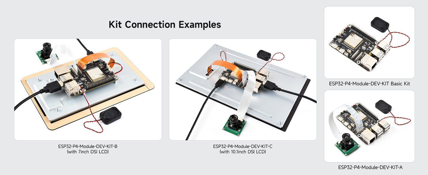
Figure 9.1: DSI Capacitive Touch Display specifications.
9.2 RPi Camera (B)

Figure 9.2: RPi Camera (B) specifications.
10. 지원 및 리소스
For further technical documentation, software examples, and community support, please visit the official Waveshare Wiki. The Wiki provides comprehensive resources to assist with your development projects.
웨이브쉐어 위키: https://www.waveshare.com/wiki


