1. 서론
This manual provides essential information for the installation, operation, and maintenance of the Cisco IE-3400-8T2S-E Catalyst IE3400 Rugged Series Network Essential Switch. This device is designed for industrial environments, offering robust network connectivity. Please read this manual thoroughly before operating the device.
2. 안전 정보
부상 및 장비 손상을 방지하기 위해 다음 안전 수칙을 준수하십시오.
- 장치의 접지가 올바르게 되어 있는지 확인하세요.
- 유지관리나 설치 절차를 수행하기 전에 전원을 분리하세요.
- Operate the switch within the specified environmental conditions (temperature, humidity).
- 자격을 갖춘 사람만이 이 장비를 설치하고 유지보수해야 합니다.
- 장치를 습기나 극한의 온도에 노출시키지 마십시오.
3. 패키지 내용
패키지에 다음 품목이 포함되어 있는지 확인하십시오.
- Cisco IE-3400-8T2S-E Catalyst IE3400 Rugged Series Network Essential Switch
- 문서(빠른 시작 가이드, 안전 정보)
- Mounting hardware (if included with specific model variant)
- Power connector terminal blocks
품목이 누락되었거나 손상된 경우 즉시 공급업체에 문의하세요.
4. 신체적 이상view
The following diagram illustrates the front panel components of the Cisco IE-3400-8T2S-E switch.
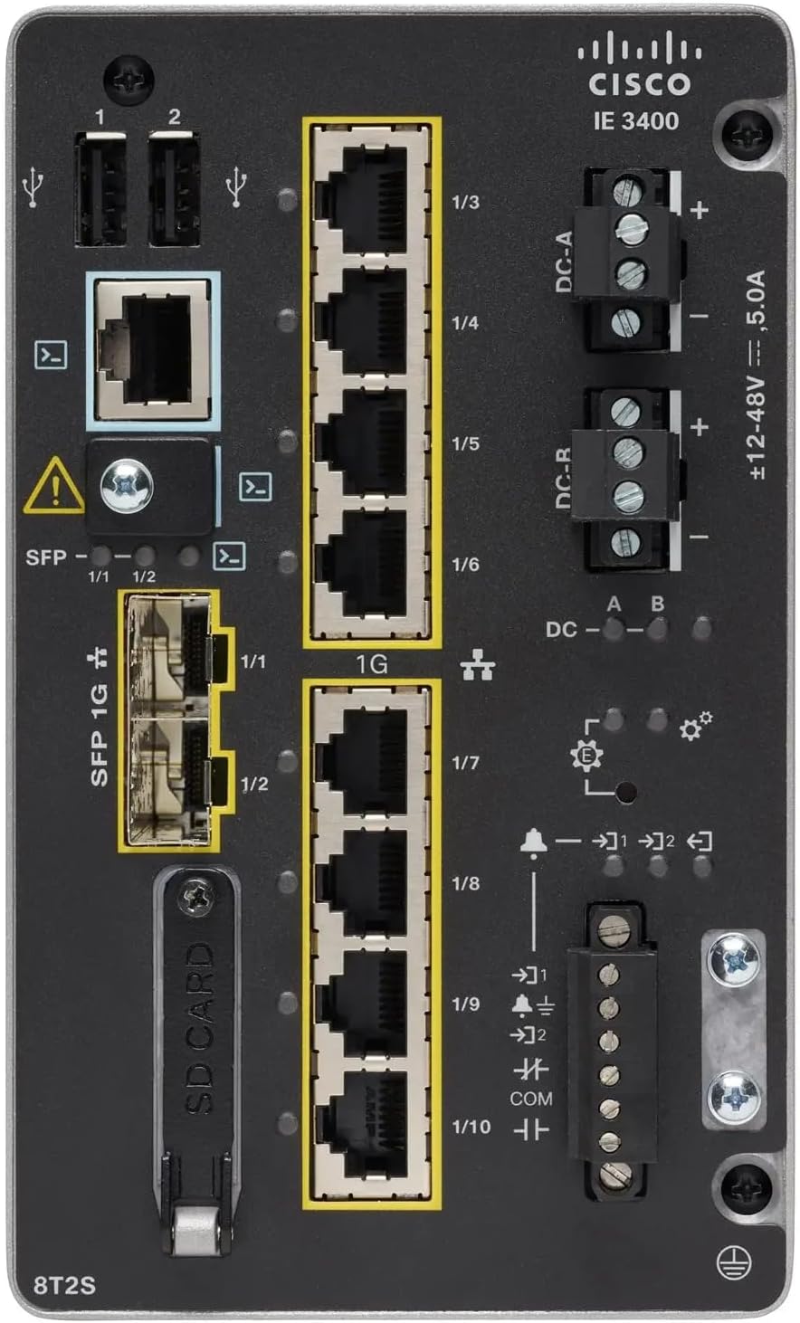
그림 1: Front Panel Layout of the Cisco IE-3400-8T2S-E Switch
4.1. Front Panel Components Description
- USB 포트(1, 2): Two USB ports for connecting external devices or for configuration.
- 콘솔 포트: An RJ45 console port for local management and initial configuration.
- SFP 1G Ports (1/1, 1/2): Two Small Form-Factor Pluggable (SFP) ports supporting 1 Gigabit Ethernet for fiber optic connections.
- 1G Ethernet Ports (1/3 - 1/10): Eight 1 Gigabit Ethernet RJ45 ports for standard network connections.
- DC Power Inputs (DC-A, DC-R): Redundant DC power input terminals, supporting a voltage range of ±12-48V at 5.0A.
- 접지 나사: Terminal for connecting the chassis to earth ground.
- SD 카드 슬롯: Slot for an SD card, typically used for configuration backup or software storage.
- Alarm/Relay Ports (1/9, 1/10): Terminals for connecting external alarm systems or relay controls.
- LED 표시등: Various LEDs indicating power status (DC A/B), system status, link/activity for ports, and alarm status.
5. 설정
5.1. 스위치 장착
The IE3400 series switches are designed for industrial environments and typically support DIN rail or wall mounting. Refer to the specific mounting instructions provided with your mounting kit for detailed steps.
5.2. 전원 연결하기
- Ensure the power source is off before connecting.
- Connect the DC power cables to the DC-A and/or DC-R terminal blocks, observing polarity (+ and -). The switch supports redundant power inputs.
- Connect the grounding wire to the grounding screw on the front panel.
- Once all connections are secure, apply power to the switch. The DC-A and/or DC-B LEDs should illuminate.
5.3. 네트워크 연결
- 이더넷 포트: Connect standard RJ45 Ethernet cables from your network devices to the 1G Ethernet ports (1/3 - 1/10).
- SFP 포트: Insert compatible SFP transceivers into the SFP 1G ports (1/1, 1/2) and connect fiber optic cables as required.
- 콘솔 포트: For initial configuration, connect a console cable from your management workstation to the RJ45 console port.
6. 사용 설명서
6.1. 초기 파워업
Upon applying power, the switch will perform a power-on self-test (POST). The system LED will indicate the boot status. Once the boot process is complete, the switch will be ready for configuration.
6.2. Configuration Access
The switch can be configured via the console port using a terminal emulator or remotely via Telnet/SSH once an IP address is assigned. Refer to the Cisco IOS documentation for detailed configuration commands and procedures.
6.3. LED 표시기
Monitor the LED indicators on the front panel to understand the switch's operational status:
- DC-A/DC-B LEDs: Indicate the status of the primary and redundant DC power inputs.
- 시스템 LED: Indicates the overall operational status of the switch (e.g., green for normal operation, amber for warning, red for fault).
- 링크/활동 LED(포트당): Indicate network link status and data activity on each Ethernet and SFP port.
- 알람 LED: Illuminates when a critical system alarm is triggered.
7. 유지관리
7.1. 청소
부드럽고 마른 천으로 스위치 외부를 정기적으로 청소하세요. 액체 또는 에어로졸 세척제는 사용하지 마세요. 통풍구에 먼지나 이물질이 없는지 확인하세요.
7.2. 펌웨어 업데이트
정기적으로 Cisco 지원을 확인하세요 website for the latest firmware updates. Applying updates can improve performance, add features, and address security vulnerabilities. Follow Cisco's official procedures for firmware upgrades.
7.3. 환경 고려 사항
Ensure the switch operates within its specified temperature and humidity ranges. Proper airflow around the device is crucial for heat dissipation.
8. 문제 해결
이 섹션에서는 일반적인 문제에 대한 기본적인 문제 해결 단계를 제공합니다.
8.1. 힘이 없다
- Verify that the power source is active and the power cables are securely connected to the DC-A/DC-R terminals.
- Check the DC-A/DC-B LEDs. If they are off, there is no power or a power supply issue.
8.2. No Network Link
- Ensure Ethernet or fiber optic cables are properly connected to both the switch port and the connected device.
- Check the Link/Activity LED for the specific port. If it is off, there is no link.
- 연결된 장치의 전원이 켜져 있고 올바르게 작동하는지 확인하세요.
8.3. System Alarm
- If the Alarm LED is illuminated, consult the Cisco IOS documentation for specific alarm codes and their meanings.
- Check system logs via the console or network management interface for detailed error messages.
9. 사양
| 특징 | 사양 |
|---|---|
| 모델 | IE-3400-8T2S-E |
| 제조업체 | 시스코 |
| 이더넷 포트 | 8 x 1 Gigabit RJ45 |
| SFP 포트 | 2 x 1 Gigabit SFP |
| 인터페이스 유형 | RJ45, SFP, PoE, PoE+ (model dependent) |
| 전원 입력 | ±12-48V DC, 5.0A (Redundant) |
| 제품 치수 | 36 x 9 x 55cm |
| 품목 무게 | 2.28 킬로그램 |
| 호환 장치 | 데스크톱, 노트북, 프린터 |
| 한국어: | 703670760433 |
10. 보증 및 지원
This product is offered as an Amazon Renewed item. Warranty and return policies are typically managed by the reseller (Amazon Renewed) for a specified period. Please refer to your purchase documentation or contact Amazon Renewed support for details regarding your specific warranty coverage.
For technical documentation, software downloads, and advanced support for the Cisco IE-3400-8T2S-E switch, please visit the official Cisco support website and search for your specific model.


