1. 서론
This manual provides detailed instructions for the installation, configuration, and operation of the MokerLink 8-Port 2.5G PoE+ 6x10G SFP+ L3 Managed Switch. This device is designed to provide high-speed network connectivity with Power over Ethernet capabilities and advanced Layer 3 management features for various network environments.
The switch features 8 x 2.5 Gigabit PoE Ethernet ports, 2 x 10 Gigabit Ethernet ports, and 4 x 10 Gigabit SFP+ optical ports, offering flexible and high-bandwidth connectivity options.
2. 패키지 내용
Verify the contents of your package. If any items are missing or damaged, please contact your vendor.
- MokerLink 8-Port 2.5G PoE+ 6x10G SFP+ L3 Managed Switch
- 전원 코드
- 랙 마운트 키트
- 사용 설명서 (본 문서)
3. 제품 오버view
The MokerLink Managed Switch offers a robust solution for demanding network applications, combining high-speed data transfer with Power over Ethernet (PoE) functionality and comprehensive Layer 3 management.
3.1 주요 특징
- 2.5G PoE Ports: 8 x 2.5Gigabit PoE Ethernet Ports (IEEE802.3bz compliant), supporting 10/100/1000M/2.5G adaptive speeds. Ports 1-8 support IEEE802.3AF/AT PoE protocol, auto-detecting compatible non-PoE devices. Maximum 30W output per port, with a total built-in power supply of 120W.
- 10Gbps 포트: 2 x 10G Ethernet Ports, backward compatible with 100M/1000M/2.5G/5Gbps rates, suitable for high-bandwidth uplink connections.
- SFP+ 포트: 4 x 10G SFP+ optical ports supporting standard 10G/2.5G/1G adaptive modules (modules not included by default).
- L3 관리 기능: 지원합니다 Web/CLI management for device and port configuration. Includes Layer 3 routing (IPV4/IPV6 Management, Routes, ARP, Loopback Interface) and Layer 2 switching features (VLAN, ACL, QoS, Jumbo frame, DHCP, security, multicast, MAC address table, diagnosis, statistics, MSTP/RSTP/STP).
- Security & Diagnosis: Features AAA/802.1X/MAC-Based authentication, DoS anti-attack, dynamic ARP inspection, DHCP Snooping, IP Source Guard, Port Security, Protected Ports, storm control. Diagnostic tools include Console/RAM/Flash Logs, Port Mirroring, Ping, Traceroute, Port Tests, UDLD Protocol.
- 유연한 관리: Supports Telnet/SSH/SNMP, Firmware Upgrade, Configuration File Download/Upload.
- 설계: Metal case, desktop/wall-mounting design, industrial-grade fan for heat dissipation.
3.2 전면 패널 레이아웃
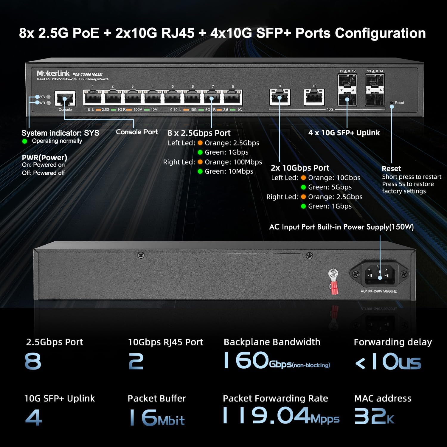
그림 1: 전면 패널view. This image displays the front panel of the switch, highlighting the Console Port, 8x 2.5Gbps PoE ports (1-8), 2x 10Gbps RJ45 ports (9-10), 4x 10G SFP+ Uplink ports (11-14), System (SYS) and Power (PWR) indicators, and the Reset button.
- SYS 지표: Indicates system operating status. Blinking rapidly may indicate an issue.
- PWR 표시기: Indicates power status. On for powered, Off for powered off.
- 콘솔 포트: RJ45 port for CLI management.
- 2.5Gbps Ports (1-8): 8x 2.5 Gigabit Ethernet ports with PoE+ support. LEDs indicate link speed (Orange: 2.5Gbps, Green: 1Gbps, Off: 100Mbps).
- 10Gbps Ports (9-10): 2x 10 Gigabit Ethernet RJ45 ports. LEDs indicate link speed (Orange: 10Gbps, Green: 5Gbps, Off: 2.5Gbps/1Gbps).
- SFP+ Uplink Ports (11-14): 4x 10 Gigabit SFP+ slots for fiber optic connections.
- 재설정 버튼: Press briefly to restart. Press and hold for 5 seconds to restore factory settings.
3.3 후면 패널 레이아웃
그림 2: 후면 패널view. This image shows the rear panel of the switch, featuring the AC Input Power Port (150W) for connecting the power cord.
- AC Input Power Port: Connects to the included power cord for AC power supply (100-240V, 50/60Hz).
4. 설정 및 설치
Follow these steps to properly install and set up your MokerLink Managed Switch.
4.1 안전 예방 조치
- 전원 공급 장치 볼륨을 확인하십시오.tage는 스위치의 요구 사항을 충족합니다.
- 환기구를 막지 마십시오.
- 스위치를 물이나 과도한 습기에 노출시키지 마십시오.
- Do not open the switch casing. 자격을 갖춘 담당자에게 서비스를 의뢰하십시오.
4.2 물리적 설치
The switch can be installed on a desktop or mounted in a rack.
데스크탑 설치
Place the switch on a flat, stable surface. Ensure adequate space around the switch for ventilation.
랙마운트 설치
Use the provided rackmount kit to install the switch into a standard 19-inch equipment rack. Secure the mounting brackets to the sides of the switch, then attach the switch to the rack using appropriate screws.

Figure 3: Rackmount Installation. This image illustrates multiple MokerLink switches mounted within a standard server rack, demonstrating the rackmount capability.
4.3 네트워크 케이블 연결
네트워크 장치를 스위치의 해당 포트에 연결하십시오.
- 2.5G PoE Ports (1-8): Use CAT5e, CAT6, or CAT7 Ethernet cables for connecting devices such as IP cameras, wireless access points, IP phones, or other network devices. These ports provide both data and power for PoE-compatible devices.
- 10G RJ45 포트(9-10): Use CAT6 (up to 55m), CAT6a, or CAT7 (up to 100m) Ethernet cables for high-speed connections to servers, other switches, or devices requiring 10 Gigabit speeds.
- 10G SFP+ 포트(11-14): Insert compatible 1G/10G SFP+ optical modules into these slots, then connect fiber optic cables for high-speed fiber uplinks or connections to other SFP+ enabled devices.

Figure 4: 2.5Gbps Port Connectivity. This image shows the 2.5Gbps ports (1-8) and indicates compatibility with CAT5e, CAT6, and CAT7 cables for connecting devices like WiFi APs, NAS, and Workstations.

Figure 5: 10Gbps Port Connectivity. This image details the 10Gbps RJ45 ports (9-10) and SFP+ ports (11-14), specifying compatible cable types (CAT6, CAT6a, CAT7) and adaptive SFP modules for connecting servers and core switches.
4.4 스위치 전원 켜기
Connect the power cord to the AC Input Power Port on the rear of the switch and then to a power outlet. The PWR indicator on the front panel should illuminate, and the SYS indicator will begin to blink as the system boots up.
5. 스위치 작동
The MokerLink Managed Switch offers various methods for configuration and management.
5.1 Initial Access and Management
스위치는 다음을 통해 관리할 수 있습니다. Web그래픽 사용자 인터페이스(GUI) 또는 명령줄 인터페이스(CLI) 기반.
Web Interface (GUI) Access
- Connect a computer to any of the switch's Ethernet ports.
- Configure your computer's IP address to be in the same subnet as the switch's default IP address (e.g., if the switch is 192.168.2.1, set your computer to 192.168.2.X, where X is not 1, with subnet mask 255.255.255.0).
- 열기 web 브라우저에 접속하여 스위치의 기본 IP 주소를 입력하세요. 192.168.2.1
- 기본 사용자 이름과 비밀번호를 입력하세요. 관리자 / 관리자
- Upon successful login, you will access the switch's management interface. It is highly recommended to change the default password immediately for security.
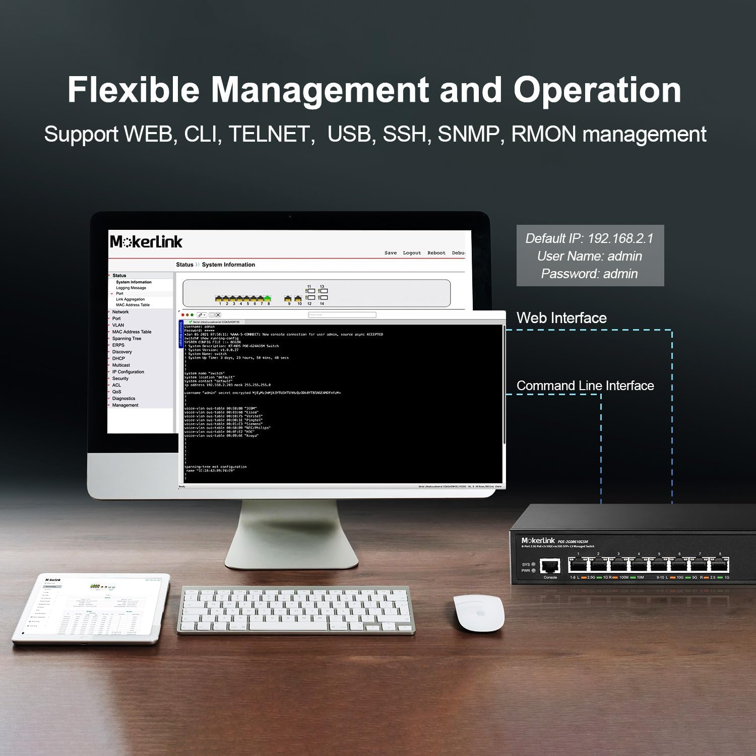
Figure 6: Flexible Management Options. This image displays both the web interface and command-line interface (CLI) for managing the MokerLink switch, along with the default IP address, username, and password.
Command Line Interface (CLI) Access
Connect to the Console port using an RJ45-to-serial cable and a terminal emulator (e.g., PuTTY, Tera Term) with the following settings:
- 통신 속도: 115200
- 데이터 비트: 8
- 패리티: 없음
- 정지 비트 : 1
- 흐름 제어: 없음
Login with the default username and password (admin/admin).
5.2 PoE 기능
The 2.5G ports (1-8) support IEEE 802.3af/at Power over Ethernet standards. The switch automatically detects and provides power to compatible Powered Devices (PDs).

Figure 7: PoE+ Support. This diagram illustrates how the switch provides power to PoE devices (IP Camera, Wireless AP, IP Phone) while also connecting to non-PoE devices (Router, Computer, NVR) for data only.
- Max 30W per PoE port.
- Total PoE Power Budget: 120W.
- The switch supplies 48V output voltage to PoE devices.
- For ports connected to non-PoE devices, it is recommended to disable PoE on those specific ports via the management interface to prevent potential issues.
5.3 Layer 2 and Layer 3 Features
The switch provides a comprehensive set of Layer 2 and Layer 3 features for advanced network management.

Figure 8: Layer 3 Managed Features. This image highlights various software features including VLAN, QoS, LACP, IGMP, ACL, DHCP, SNMP, Route, and Security.
VLAN(가상 로컬 영역 네트워크)
VLANs allow you to segment your network into logical broadcast domains, improving security and performance. The switch supports 802.1Q Tag-based VLANs.

Figure 9: VLAN Configuration. This diagram illustrates how 802.1Q Tag-based VLANs can segregate network traffic for different device types (e.g., IP cameras, wireless APs, IP phones) without requiring separate physical equipment.
QoS(서비스 품질)
QoS allows you to prioritize network traffic, ensuring critical applications (like voice or video) receive sufficient bandwidth and low latency.

Figure 10: QoS Prioritization. This diagram shows how QoS prioritizes different types of network traffic, such as high priority for audio, medium for video, and low for general data, to reduce packet loss and latency.
Link Aggregation (LACP)
LACP (Link Aggregation Control Protocol) allows you to group multiple physical links into a single logical link, increasin대역폭을 높이고 이중화를 제공합니다.

Figure 11: Link Aggregation. This diagram illustrates how LACP combines multiple Ethernet connections between the MokerLink switch and other devices (like another switch or a NAS) to increase bandwidth and improve resilience.
계층 3 라우팅
The switch supports IPV4/IPV6 routing, ARP, and Loopback Interface management, enabling inter-VLAN routing and more complex network topologies.
보안 기능
Implement security measures such as AAA/802.1X/MAC-Based authentication, DoS anti-attack, dynamic ARP inspection, DHCP Snooping, IP Source Guard, Port Security, Protected Ports, and storm control to protect your network.
6. 유지관리
정기적인 유지관리를 통해 스위치의 최적의 성능과 수명을 보장할 수 있습니다.
6.1 펌웨어 업그레이드
Firmware updates can provide new features, performance improvements, and security patches. Refer to the management interface for firmware upgrade options. It is recommended to download firmware from the official MokerLink support channels. As of current information, firmware updates may not be publicly available on the manufacturer's website, and direct contact might be required.
6.2 구성 백업 및 복원
Regularly back up your switch configuration to prevent data loss. The management interface (Web GUI or CLI) provides options to download the current configuration file 저장된 구성을 업로드합니다. file.
CLI Command Examp르 : copy running-config startup-config to save current configuration.
6.3 환경 고려 사항
Ensure the switch is operated within its specified temperature and humidity ranges. The industrial-grade fan assists with heat dissipation, but proper airflow around the unit is crucial.

Figure 12: Design and Efficiency. This image highlights the switch's features such as Energy Efficient Ethernet (EEE), durable metal casing, and overall energy-saving design, with arrows indicating airflow for cooling.
7. 문제 해결
이 섹션에서는 일반적으로 발생할 수 있는 문제에 대한 해결책을 제공합니다.
7.1 No Power / System Indicator Off
- 전원 코드가 스위치와 전원 콘센트에 모두 안전하게 연결되어 있는지 확인하세요.
- 전원 콘센트가 작동하는지 확인하세요.
- Check the power supply unit for any visible damage.
7.2 No Link Light / No Connectivity
- 이더넷 케이블의 양쪽 연결 상태를 확인하십시오. 다른 케이블을 사용해 보십시오.
- 연결된 장치의 전원이 켜져 있고 올바르게 작동하는지 확인하세요.
- Verify the port status in the switch's management interface.
- SFP+ 포트의 경우, SFP+ 모듈이 올바르게 삽입되어 호환되는지, 그리고 광섬유 케이블이 손상되지 않았는지 확인하세요.
7.3 PoE 장치가 켜지지 않음
- Confirm the connected device is PoE-compatible (IEEE 802.3af/at).
- Check the PoE status of the port in the switch's management interface. Ensure PoE is enabled for that port.
- Verify the power requirements of the PD do not exceed 30W per port or the total 120W budget.
- If connecting a non-PoE device to a PoE port, it is recommended to disable PoE on that port to prevent potential damage to the non-PoE device.
7.4 네트워크 성능 문제
- Check for network loops. The switch supports loop detection to help identify and resolve these.
- Utilize QoS settings to prioritize critical traffic.
- Review port statistics and logs in the management interface for errors or high utilization.

Figure 13: Loop Detection. This diagram illustrates how the loop detection feature helps identify and remove network loops between switches or devices, preventing network slowdowns or outag에스.
7.5 공장 기본값으로 재설정
If you forget the login credentials or encounter persistent configuration issues, you can reset the switch to its factory default settings. With the switch powered on, press and hold the 리셋 버튼 on the front panel for approximately 5 seconds until the SYS LED blinks rapidly, then release. The switch will reboot with default settings.
8. 사양
| 특징 | 설명 |
|---|---|
| 모델 번호 | 8x2.5G POE + 6x10G SFP Managed |
| 인터페이스 유형 | PoE, SFP+ |
| 포트 수 | 8x 2.5G PoE, 2x 10G Ethernet, 4x 10G SFP+ |
| PoE 표준 | IEEE 802.3af / at |
| 총 PoE 전력 예산 | 120와트 |
| 데이터 전송 속도 | 10 Gigabits Per Second (max) |
| 백플레인 대역폭 | 160Gbps (비 차단) |
| 패킷 버퍼 | 16메가비트 |
| 패킷 전달 속도 | 119.04메가피에스 |
| MAC 주소 테이블 크기 | 32K |
| 관리 | Web GUI, CLI (Console, Telnet, SSH), SNMP |
| Layer Features | L2 (VLAN, QoS, LACP, STP), L3 (Static Routing, ARP) |
| 치수 | 14.25 x 11.5 x 3.27 인치 |
| 품목 무게 | 5.06파운드 |
| 케이스 소재 | 금속 |
| 색상 | 검은색 |
| 포함된 구성 요소 | 2.5G POE Switch, Power Cord, Rackmount Kit |
9. 보증 및 지원
MokerLink products typically come with a standard manufacturer's warranty. Please refer to the product packaging or the official MokerLink web구체적인 보증 약관은 해당 사이트에서 확인하세요.
For technical support, product inquiries, or to obtain the latest firmware updates, it is recommended to contact MokerLink directly through their official support channels. As noted in some user reviews, direct support may be the primary method for obtaining detailed documentation or firmware beyond what is included with the product.
일반적인 정보는 다음 웹사이트를 방문하세요. MokerLink Store on Amazon.


