1. 서론
The AdaLov CPE881 3-Pack Wireless Bridge system is designed to extend network connectivity over long distances, providing a stable and high-speed wireless link. This system supports both Point-to-Point (PTP) and Point-to-Multipoint (PTMP) configurations, making it suitable for various outdoor networking needs such as connecting remote buildings, extending internet to surveillance cameras, or providing network access in large properties.
Operating on the 5.8GHz frequency band, the CPE881 offers enhanced speed and reduced interference. Each bridge features two 1000Mbps LAN ports for reliable wired connections and a 14dBi high-gain antenna for a working distance of up to 5KM (3.1 miles) with a clear line of sight. The devices are IP65-rated for outdoor use, ensuring durability in various weather conditions.

Image 1.1: AdaLov CPE881 Wireless Bridges
2. 패키지 내용
아래 나열된 모든 품목이 패키지에 포함되어 있는지 확인하십시오. 누락되거나 손상된 품목이 있는 경우 고객 지원 센터로 문의하십시오.
- 3 x Wireless Bridges (AdaLov CPE881)
- 3 x POE Adapters
- 3 x 금속 케이블 타이
- 3 x 네트워크 케이블
- 1 x 사용자 설명서

이미지 2.1: 패키지 구성품
3. 제품 오버view
3.1. 장치 구성 요소
Each CPE881 wireless bridge features the following components:
- 디지털 튜브 디스플레이: Shows the current operating mode (Transmitter A Mode, Receiver B Mode) and pairing status.
- 재설정 버튼: Used to reset the device to factory settings or initiate pairing.
- AB 버튼: Used to switch between Transmitter (A) and Receiver (B) modes during setup.
- DC 전원 포트: 전원 어댑터를 연결합니다.
- LAN (1000Mbps) Ports: Two Gigabit Ethernet ports for wired network connections.
- LED 표시등: Provide visual feedback on WLAN status, signal strength, LAN activity, and power.
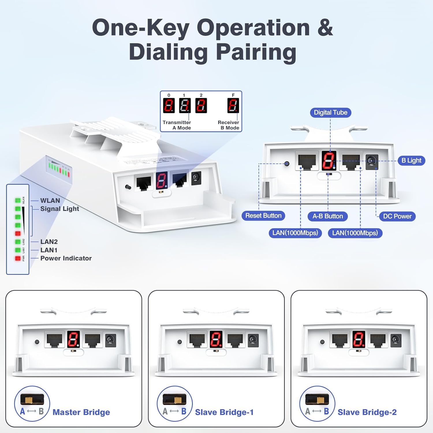
Image 3.1: CPE881 Device Components and Indicators
3.2. LED 표시기
| 지시자 | 상태 | 설명 |
|---|---|---|
| 힘 | 솔리드 레드 | 장치의 전원이 켜져 있습니다. |
| LAN1 / LAN2 | Green (Solid/Flashing) | Solid: Wired connection established. Flashing: Data activity. |
| 무선랜 | Green (Solid/Flashing) | Solid: Wireless link established. Flashing: Wireless data activity. |
| 신호등 | Green/Red LEDs | Indicates wireless signal strength. More green LEDs mean stronger signal. |
4. 설정 지침
The CPE881 bridges are designed for simple plug-and-play setup using a dialing pairing method. This section outlines the steps for both Point-to-Point (PTP) and Point-to-Multipoint (PTMP) configurations.
4.1. Point-to-Point (PTP) Setup
In a PTP setup, two CPE881 devices establish a direct wireless link to extend a network connection between two locations.
- Identify Devices: Designate one CPE881 as the 마스터 브리지 (Transmitter A) and the other as the 슬레이브 브리지 (Receiver B).
- 전원 켜기: Connect both bridges to their respective POE adapters and power them on.
- Configure Master Bridge: On the Master Bridge, press the A-B button until the digital tube displays 'A'. This sets it as the transmitter.
- Configure Slave Bridge: On the Slave Bridge, press the A-B button until the digital tube displays 'B'. This sets it as the receiver.
- 편성: The devices will automatically attempt to pair. Once paired, the WLAN and Signal LEDs on both devices will indicate a stable connection.
- 네트워크에 연결:
- Connect the Master Bridge's LAN port to your main router or network switch.
- Connect the Slave Bridge's LAN port to the device or local network you wish to extend (e.g., another router, computer, or security camera system).
- 최적 정렬: For best performance, ensure a clear line of sight between the two bridges and align them directly towards each other. The signal strength LEDs will help in achieving optimal alignment.

Image 4.1: Point-to-Point Configuration Example
4.2. Point-to-Multipoint (PTMP) Setup
A PTMP setup uses one Master Bridge to connect with multiple Slave Bridges, extending network coverage to several locations simultaneously.
- Identify Devices: Designate one CPE881 as the 마스터 브리지 (Transmitter A) and the remaining two as Slave Bridges (Receiver B-1 and Receiver B-2).
- 전원 켜기: Connect all three bridges to their respective POE adapters and power them on.
- Configure Master Bridge: On the Master Bridge, press the A-B button until the digital tube displays 'A'.
- Configure Slave Bridges: On the first Slave Bridge, press the A-B button until the digital tube displays 'B'. On the second Slave Bridge, press the A-B button until the digital tube displays 'B'.
- 편성: The Master Bridge will automatically pair with all Slave Bridges set to 'B' mode. The WLAN and Signal LEDs on all devices will indicate a stable connection.
- 네트워크에 연결:
- Connect the Master Bridge's LAN port to your main router or network switch.
- Connect each Slave Bridge's LAN port to the respective device or local network at each remote location.
- 최적 정렬: For PTMP, the Slave Bridges must be positioned in front of the Master Bridge. The Master Bridge and Slave Bridges must face each other, and the maximum angle between the Master Bridge and any Slave Bridge should not exceed 60 degrees for optimal signal.
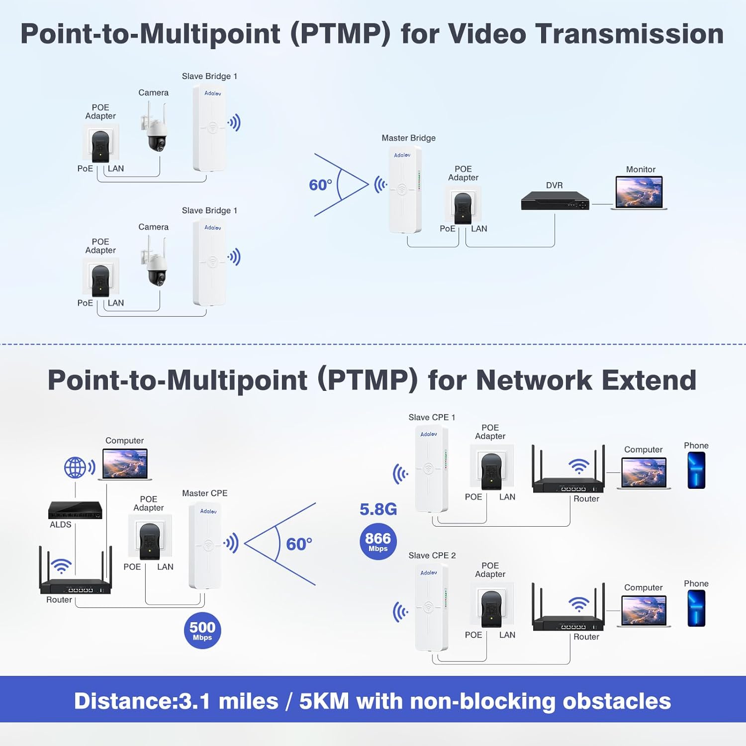
Image 4.2: Point-to-Multipoint Configuration Examp레

Image 4.3: PTMP Connection Rules
5. 사용 설명서
Once the CPE881 bridges are set up and paired, they operate automatically to maintain the wireless link. Here are some operational considerations:
- 신호 모니터링: Regularly check the Signal Light LEDs on each bridge. A higher number of green LEDs indicates a stronger and more stable connection. If signal strength is low, consider adjusting the alignment or checking for new obstructions.
- 네트워크 통합: The CPE881 acts as a transparent bridge. Devices connected to the Slave Bridge's LAN port will receive network access from the Master Bridge's network, as if directly connected via an Ethernet cable.
- 고속 성능: The 5.8GHz frequency band and Gigabit LAN ports are designed for high-speed data transfer. For optimal throughput, ensure your connected devices and network infrastructure also support Gigabit speeds.
- PoE(Power over Ethernet): The included PoE adapters simplify installation by providing both power and data over a single Ethernet cable, reducing cable clutter.
6. 유지관리
The AdaLov CPE881 is designed for minimal maintenance due to its robust construction.
- 비바람에 견디는 디자인: The IP65 rating ensures the devices are dustproof and waterproof, suitable for harsh outdoor conditions. No special weather protection is typically required.
- 청소: Periodically inspect the exterior of the devices for dirt or debris buildup. Clean with a soft, damp 필요한 경우 천으로 닦으십시오. 독한 화학 약품이나 연마제를 사용하지 마십시오.
- 펌웨어 업데이트: 제조사 확인해보세요 website periodically for any available firmware updates. Follow the provided instructions carefully for any update process.
- 케이블 검사: Ensure all network and power cables are securely connected and free from damage.

Image 6.1: IP65 Outdoor Weather Resistance
7. 문제 해결
If you encounter issues with your AdaLov CPE881 wireless bridges, refer to the following common troubleshooting steps:
- 전원 없음:
- Ensure the POE adapter is correctly connected to a power outlet and the bridge.
- 전원 콘센트가 작동하는지 확인하세요.
- No Wireless Link (WLAN LED Off/Flashing Red):
- Check if the Master and Slave bridges are correctly configured (Master 'A', Slave 'B').
- Ensure there is a clear line of sight between the bridges. Obstructions like trees or buildings can severely degrade signal.
- Adjust the physical alignment of the bridges to face each other directly. Use the Signal Light LEDs to optimize alignment.
- Ensure the distance between bridges does not exceed the maximum recommended range (5KM/3.1 miles).
- Low Signal Strength (Few Green Signal LEDs):
- Improve line of sight by removing obstructions or adjusting mounting height.
- Fine-tune the alignment of the bridges. Even small adjustments can significantly improve signal.
- No Network Access (LAN LED Off/No Data):
- Verify that the Ethernet cables are securely connected to the LAN ports on both the bridge and the connected device/router.
- Test the Ethernet cables with another device to ensure they are functional.
- Ensure the main router connected to the Master Bridge is providing internet access.
- Difficulty with Point-to-Multipoint (PTMP) Setup:
- Confirm all Slave Bridges are set to 'B' mode.
- Ensure all Slave Bridges are within the 60-degree angular range of the Master Bridge and have a clear line of sight.
- 공장 기본값으로 재설정: If issues persist, you can reset a bridge to its factory default settings by pressing and holding the Reset button for approximately 5-10 seconds until the LEDs flash. After resetting, reconfigure the device.
8. 사양
| 특징 | 세부 사항 |
|---|---|
| 모델명 | CPE881 |
| 제품 치수 | 3.54 x 2.16 x 9.84 인치 |
| 품목 무게 | 4.27파운드(팩당) |
| 주파수 대역 클래스 | 단일 대역(5.8GHz) |
| 무선 통신 표준 | 802.11a, 802.11ac, 802.11n |
| 무선 속도 | 최대 866Mbps |
| LAN Data Rate | 최대 500Mbps |
| 연결 기술 | 이더넷 |
| LAN 포트 | 2 x 1000Mbps Gigabit LAN Ports |
| 안테나 유형 | Internal 14dBi High-Gain Directional Antenna |
| 작업 거리 | Up to 5KM (3.1 miles) with Line of Sight (LOS) |
| 특별 기능 | Access Point Mode, Directional Antenna, LED Indicator, Weatherproof (IP65) |
| 장착 옵션 | Pole or Wall-mounted |
| 호환 장치 | Computer, Router, Security Camera, Starlink, Switch (Note: Do not use 48V POE switch to power) |

Image 8.1: CPE881 Product Dimensions
9. 보증 및 지원
AdaLov products are designed for reliability and performance. Your CPE881 3-Pack Wireless Bridge comes with a customer service guarantee.
- 보증 정보: For specific warranty terms and conditions, please refer to the documentation included with your purchase or visit the official AdaLov web대지.
- 기술 지원: If you require technical assistance, have questions about installation, or encounter any issues not covered in this manual, please contact AdaLov customer support. Contact details can typically be found on the product packaging, the official AdaLov web사이트나 구매처를 통해 구매할 수 있습니다.

