1. 서론
The WANLUTECH CT-66 Multifunction Cable Tester is designed for comprehensive cable testing, including wire tracing, continuity checking, RJ45 cable fault detection, and telephone line status testing. This device consists of an Emitter and a Receiver, providing efficient and accurate results for network and telecommunication professionals.
2. 제품 오버view
2.1 Receiver (Wire Tracker Wand)

This image displays the CT-66 Receiver, also known as the Wire Tracker Wand, highlighting its various components. Key features include an LED light for illumination, a Power Indicator, and a UTP cable sequence/signal strength indicator. It also features an Earphone port for use in noisy environments, a Shielded cable continuity indicator, and a Sensitivity adjustment knob to fine-tune tracing. Additional ports and indicators are present for UTP cable testing, mode selection (SCAN, NCV), RJ45 status, UTP cable type, 100M/1000M detection, and a PD Powered test port.
2.2 Emitter (Wire Tracker)

This image illustrates the CT-66 Emitter, detailing its interfaces and controls. It includes a BNC interface and UTP/Scan port for various cable connections. Indicators for Telephone status, LOCAL/Remote end continuity, and Battery status are visible. The device features a Functions switch, a SET button for various functions, and indicators for UTP cable sequence, UTP cable type, Cable tracer mode, and 100M/1000M network speed.
3. 설정
3.1 패키지 내용
The package includes the CT-66 Emitter, CT-66 Receiver, a carrying tool bag, an RJ45 cable, and a BNC alligator clip cable. Please note that AA batteries are not included and must be purchased separately for operation.
3.2 배터리 설치
Install the required AA batteries into both the Emitter and Receiver units. Ensure correct polarity during installation.
3.3 언박싱 및 초기 설정 영상
This video demonstrates the unboxing process of the CT-66 Multifunction Cable Tester, showing the included components such as the Emitter, Receiver, carrying bag, and various cables. It also illustrates the battery installation for both units and provides a brief overview of the cable tracing and continuity testing functions. The video covers coaxial cable alligator clip testing, RJ45 fault detection, cable tracing, and network cable port continuity detection.
4. 사용 설명서
4.1 케이블 추적
To trace a cable, connect one end of the cable to the Emitter's BNC or RJ11 port. If the cable lacks a connector, use the provided alligator clips to connect to the bare copper wire. Turn on the Emitter and select the appropriate mode. Use the Receiver wand to scan along the cable path. The Receiver will emit an audible tone and illuminate LEDs to indicate the presence and strength of the signal, helping to locate the target cable.

This image demonstrates the simultaneous cable tracing and UTP cable testing function. The Emitter is connected to a network cable, and the Receiver is actively tracing the cable, indicated by its illuminated signal strength LEDs. The UTP cable is also connected to the Receiver for continuity testing, showcasin이 장치의 이중 기능을 활용합니다.
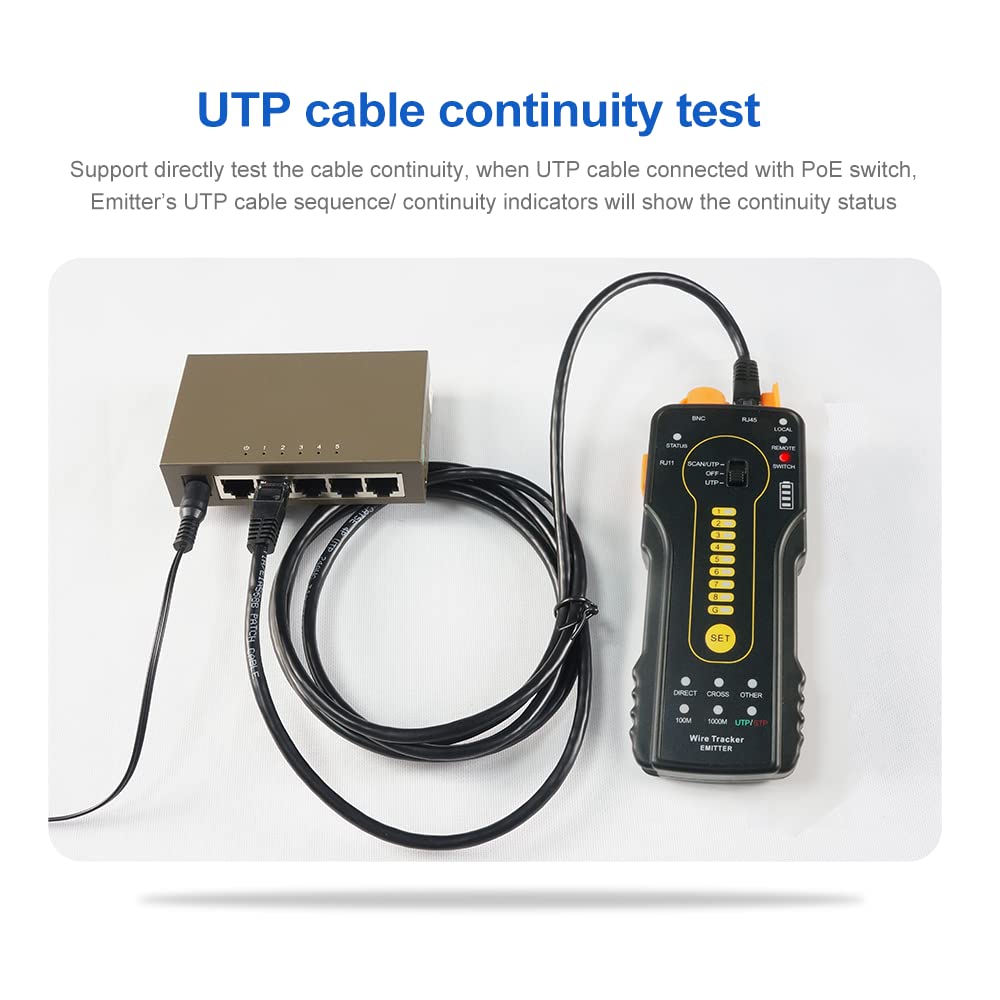
4.2 Continuity Testing (UTP/STP/RJ45/RJ11)
Connect the cable to be tested to the corresponding ports on both the Emitter and Receiver. The device will automatically scan the cable for continuity. The LED indicators on both units will light up sequentially, indicating the status of each wire. If a wire is broken or short-circuited, the corresponding LED will not light up or will show an error pattern.

This image illustrates a UTP cable continuity test. The Emitter is connected to a network switch, and the Receiver is connected to the other end of the UTP cable. The Emitter's indicators display the continuity status, demonstrating the device's ability to test cables even when connected to a Power over Ethernet (PoE) switch, supporting up to 60V withstand voltage.
4.3 RJ45 Cable Plug Fault Quick Test
Connect the RJ45 cable to the Emitter. The 'LOCAL' indicator shows the RJ45 cable plug status of the Emitter. A lit indicator means normal, while an unlit indicator means a fault. The 'REMOTE' indicator shows the RJ45 cable plug status of the Receiver. This allows for quick identification of faults in RJ45 connectors.

This image shows the RJ45 cable plug fault quick test. The Emitter is connected to an RJ45 cable, and its numbered indicators display the continuity of each pin. In this example, pin 1 is shown as disconnected (marked with an 'X'), indicating a fault in the cable or connector.
4.4 Locate Short-Circuit Position
When tracing a wire, if the Receiver does not emit a 'buzzed' sound, it indicates a short-circuit position. This feature helps pinpoint the exact location of a short in a cable.

This image demonstrates how to locate a short-circuit in a cable using the CT-66. The Emitter is connected to one end of the cable, and the Receiver is used to trace the signal. The absence of a signal or a change in the signal pattern at a specific point indicates a short-circuit, as highlighted in the image.
4.5 Cable Type Detection (100M/1000M, Straight/Cross/Other)
The device can identify the cable type (100M/1000M, straight/cross/other). When a 1000M Straight network cable is connected, the 1000M and Straight cable type indicators will remain lit. This eliminates the need to view running cable sequence or continuity indicators for basic cable type identification.

This image illustrates the cable type detection feature. The Emitter displays indicators for 'DIRECT', 'CROSS', 'OTHER', '100M', '1000M', and 'UTP/STP'. When a 1000M Straight network cable is connected, the '1000M' and 'DIRECT' indicators will light up, providing quick identification of the cable's characteristics.
4.6 Telephone Line Status Test
Connect the telephone line to the RJ11 port on the Emitter. The 'PHONE' indicator will show the line status: unlit for off-hook, lit for standby, and flashing for ringing. This allows for quick assessment of telephone line functionality.

This image shows the CT-66 Emitter conducting a telephone line status test. An RJ11 cable is connected to the 'PHONE' port, and the 'PHONE' indicator is illuminated, signifying a standby line status. The accompanying text clarifies that an unlit indicator means the line is off-hook, a lit indicator means standby, and a flashing indicator means the line is ringing.
4.7 Shielding Layer Continuity Test
The device can test the continuity of a cable's shielding layer. Connect the shielded cable to the Emitter. The 'G' indicator light will illuminate if the shielding is normal. If the 'G' indicator is off, it signifies that the shielding layer is broken.
This image illustrates the shielding layer continuity test. The CT-66 Emitter is connected to a shielded cable, and the 'G' indicator light is illuminated, confirming that the cable's shielding is continuous and intact. An inset image provides a visual reference of a shielded cable's internal construction.
4.8 PoE Switch Live Tracing
The UTP port supports a maximum 60V withstand voltage, allowing the wire to be traced directly when connected to a PoE switch. This functionality simplifies work by enabling tracing without disconnecting the PoE power source.

This image demonstrates the PoE switch live tracing capability. The CT-66 Emitter is connected to a PoE switch, and the Receiver is used to trace a connected cable. The image emphasizes the device's 60V withstand voltage, ensuring safe operation when tracing cables connected to active PoE switches.
4.9 PoE Switch Detection
The device can check if a PoE switch is supplying power normally. If the indicator lights are on, it signifies a non-standard PoE switch. If the indicator lights flash, it means it's a standard PoE switch. The device supports 24V/48V PoE switches.

This image shows the CT-66 Emitter performing PoE switch detection. The device is connected to a network port, and its LED indicators display the PoE power status. Solid lights indicate a non-standard PoE switch, while flashing lights indicate a standard 24V/48V PoE switch.
4.10 Positive / Negative Polarity Detection
The device can detect positive and negative polarity. If the indicator light is red, the red wire clip is negative and the black wire clip is positive. If the indicator light is green, the black wire clip is negative and the red wire clip is positive. The brightness of the indicator light corresponds to the voltage level: brighter for higher levels, darker for lower levels. This function is for voltages below DC100V.

This image demonstrates the positive/negative polarity detection feature. The CT-66 Emitter is connected to a 9V battery using alligator clips. The indicator light's color (red or green) determines the polarity of the clips, and its brightness reflects the voltage level. This test is applicable for voltages below DC100V.
4.11 100M/1000M Switch Judgement
Connect one end of a network cable to a switch and the other end to the Emitter's RJ45 port. Press the 'SET' key to switch to 'SWITCH' mode. If the 1, 2, 3, 6 indicators light on, it indicates a 100M switch. If 1, 2, 3, 4, 5, 6, 7, 8 indicators light on, it indicates a 1000M switch.

This image illustrates the 100M/1000M switch judgment function. The CT-66 Emitter is connected to a network switch, and the display shows two distinct patterns of illuminated pins. The pattern with pins 1, 2, 3, and 6 lit indicates a 100M switch, while the pattern with pins 1 through 8 lit indicates a 1000M switch.
4.12 감도 조정
Adjust the knob on the Receiver to change its sensitivity. When cables are too close and difficult to distinguish, adjust to low sensitivity to track the specific cable more accurately.
4.13 무음 모드
Long press the 'MUTE' key on the Receiver to activate silent mode. In this mode, the signal strength indicator lights are used to trace the wire without audible feedback. When the strongest signal is received, all eight indicator lights will be on. Press 'MUTE' again to exit silent mode.
5. 사양
| 특징 | 사양 |
|---|---|
| 제조업체 | 완루테크 |
| 모델 번호 | CT-66 |
| 품목 무게 | 472g |
| 소포 크기 | 24.51 x 17.2 x 4.7cm |
| 스타일 | 케이블 테스터 |
| 전원 유형 | 배터리 구동 |
| 필요한 배터리 | 예 (포함되지 않음) |
| 포함된 구성 요소 | Cable tracer (Emitter and Receiver) |
| 최소 운영 볼륨tage | 60 볼트 |
| 최대 작동 볼륨tage | 60 볼트 |


