1. 서론
The UCTRONICS RD6012 is a 720W DC step-down converter and stabilized power supply module. It is designed to provide a constant voltage (DC 0.0V-60V) and constant current (0.0A-12A) output from an input voltage range of DC 6.0V-70V. This manual provides essential information for the safe and effective operation of your RD6012 power supply module.

Figure 1: UCTRONICS RD6012 DC Power Supply Converter and included accessories. This image displays the main unit along with the banana plug to alligator clips, external temperature sensor probe, and Micro USB cable.
2. 패키지 내용
Upon opening the package, please verify that all the following items are present:
- 1 × UCTRONICS RD6012 Power Supply Module
- 1 pair × Banana Plug to Alligator Clips (Red and Black)
- 1 × External Temperature Sensor Probe
- 1 × 마이크로 USB 케이블
3. 제품 오버view 및 제어
The RD6012 features a 2.4-inch color LCD display for clear readings and multiple buttons for intuitive operation. Understanding the layout of the controls is essential for proper use.

Figure 2: Front panel layout and control identification. This image provides a detailed view of the RD6012's front panel, labeling each button, port, and display area for easy reference.
전면 패널 구성 요소:
- A: 전원 버튼 - Controls the main power to the unit.
- B: Second Function Button - Used for accessing secondary functions or menus.
- C: Rapid Storage Button - For quick saving of settings.
- D: Current/Over Current Protection Value Setting - Adjusts output current and OCP limit.
- 이: 권tage/오버 볼륨tage 보호 값 설정 - Adjusts output voltage and OVP limit.
- F: Micro USB Interface - For communication with a PC.
- G: Power Output/Battery Charging Negative Pole - Negative terminal for output.
- H: Battery Charging Positive Pole - Positive terminal for battery charging.
- I: Power Output Positive Pole - Positive terminal for output.
- J: Output Switch - Toggles the output power on/off.
- K: Encoder Potentiometer/Cancel Button - Rotary knob for value adjustment and menu navigation, also acts as a cancel button.
- L: 화살표 키 - For navigation within menus.
- M: Keypad - Numeric input for precise value setting.
- N: LCD Display - Shows voltage, current, power, and other operational parameters.
4. 사양
The following table details the technical specifications of the UCTRONICS RD6012 power supply module:
| 매개변수 | 값 |
|---|---|
| 입력 Voltage | 직류 6.0V-70.0V |
| 출력 볼륨tage | 직류 0V-60.0V |
| 출력 전류 | 0-12.0A |
| 출력 전력 | 0-720W |
| 입력 Voltage 정확도 | ±(1% + 5자리) |
| 출력 볼륨tage 정확도 | ±(0.3% + 3자리) |
| 출력 전류 정확도 | ±(0.5% + 5자리) |
| 디스플레이 화면 | 2.4인치 컬러 LCD 디스플레이 |
| External Temperature Range | 0°F-200°F (approx. -17.8°C to 93.3°C) |
| Intelligent Temperature-Controlled Fan | Temperature trigger: 113°F (45°C); Current Trigger: 8A |
| 전체 치수 | 167mm × 81mm × 65mm |
| 순중량 | 330g |
| 안전 보호 | Anti-reverse protection, Overvoltage Protection (OVP), Overcurrent Protection (OCP), Over-temperature Protection (OTP, upper limit 80°C/176°F) |
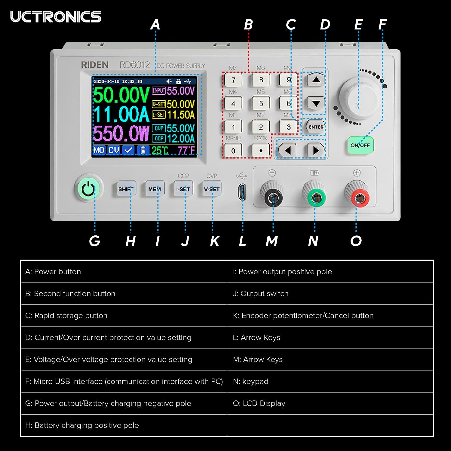
Figure 3: Physical dimensions of the RD6012 module. This image illustrates the length, width, and height of the power supply unit in millimeters and inches.
5. 안전 정보
Please read and understand all safety warnings before operating the device to prevent injury or damage.
- Ensure the input power is within the specified range of DC 6V to 70V. Operating outside this range may cause damage to the device or improper function.
- If the output short circuit occurs when the Overcurrent Protection (OCP) value is set lower than the I-SET value, the device will automatically shut off for protection. If the OCP value is set higher, a short circuit will cause the device to switch to constant current output mode.
- Non-professionals should not use the battery charging function without proper knowledge and precautions. Improper use carries a risk of fire and explosion.
- This module is not suitable for charging batteries with a charging limit voltage 60V를 초과합니다.
- Always ensure proper ventilation around the unit to prevent overheating.
- 장치를 습기나 극한의 온도에 노출시키지 마십시오.
6. 설정
The RD6012 module requires an external DC power source for operation. It is designed to be integrated into a larger system or enclosure.
6.1. Input Power Connection
- Ensure the external DC power source is turned off and disconnected from mains power.
- Connect the positive (+) terminal of your DC input power source (6V-70V) to the input positive terminal of the RD6012 module.
- Connect the negative (-) terminal of your DC input power source to the input negative terminal of the RD6012 module.
- Double-check all connections for polarity and security.
6.2. Output Load Connection
- With the RD6012 output switch (J) in the OFF position, connect your load to the output terminals (G for negative, I for positive).
- If using the battery charging function, connect the battery to terminals G (negative) and H (positive), ensuring correct polarity.
6.3. External Temperature Sensor Connection
Plug the external temperature sensor probe into the designated port on the front panel to monitor external temperatures.
6.4. PC Communication (Optional)
Connect the Micro USB cable from the RD6012's Micro USB interface (F) to your computer for PC control and monitoring. Refer to the UCTRONICS website for software and driver downloads.
Figure 4: RD6012 connected to a PC for software control. This image demonstrates the power supply module interfaced with a computer, displaying the graphical user interface of the control software.
7. 사용 설명서
After successful setup, you can begin operating the RD6012.
7.1. 전원 켜기
Turn on your external DC input power source. The RD6012 display should illuminate. Press the Power Button (A) if the unit does not power on automatically.
7.2. 출력 볼륨 설정tage와 현재
- 볼륨 사용tage/오버 볼륨tage Protection Value Setting button (E) to select the voltage setting mode.
- Rotate the Encoder Potentiometer (K) to adjust the desired output voltage. Press the encoder to confirm or use the keypad (M) for direct input.
- Use the Current/Over Current Protection Value Setting button (D) to select the current setting mode.
- Rotate the Encoder Potentiometer (K) to adjust the desired output current limit. Press the encoder to confirm or use the keypad (M) for direct input.
7.3. Enabling Output
한 번 권tage and current limits are set, press the Output Switch (J) to enable the power output to your connected load. The display will show the actual output voltage, 전류 및 전력.
7.4. Using Memory Functions
The RD6012 allows you to store and recall frequently used voltage and current settings. Refer to the on-screen menu for detailed instructions on saving and loading memory presets using the Rapid Storage Button (C) and other navigation controls.
8. 유지관리
To ensure the longevity and reliable operation of your RD6012, follow these maintenance guidelines:
- 청소: Disconnect the unit from all power sources before cleaning. Use a soft, dry cloth to wipe the exterior. Do not use abrasive cleaners or solvents.
- 통풍: Ensure the fan and ventilation openings are free from dust and obstructions. The intelligent temperature-controlled fan will activate as needed to maintain optimal operating temperature.
- 저장: Store the device in a cool, dry environment away from direct sunlight and excessive humidity when not in use.
- 점검: Periodically inspect cables and connections for any signs of wear or damage.
9. 문제 해결
If you encounter issues with your RD6012, consider the following common troubleshooting steps:
- 전원/디스플레이 없음:
- Check if the input power source is connected and supplying voltage within the 6V-70V range.
- Ensure the power button (A) is pressed.
- Verify the input power cable connections are secure.
- 출력 없음tag현재:
- Ensure the output switch (J) is in the ON position.
- Check if the set output voltage 및 전류 제한은 부하에 적합합니다.
- Verify that Overvoltage Protection (OVP) or Overcurrent Protection (OCP) has not been triggered. Adjust OVP/OCP settings if necessary.
- Inspect the output load connections for shorts or open circuits.
- 과열:
- 장치 주변에 적절한 환기가 이루어지도록 하세요.
- Check if the fan is operating when the unit is under load or at higher temperatures.
- Reduce the load or operating time if the unit consistently overheats.
- PC Communication Issues:
- Ensure the correct drivers are installed on your computer.
- Verify the Micro USB cable is securely connected to both the RD6012 and the PC.
- 다른 USB 포트나 케이블을 사용해 보세요.
For persistent issues not resolved by these steps, please contact UCTRONICS customer support.
10. 보증 및 지원
For information regarding warranty coverage, technical support, or service, please refer to the documentation provided at the time of purchase or visit the official UCTRONICS web사이트. 보증 청구를 위해 구매 증빙 자료로 구매 영수증을 보관하세요.


