1. 제품 오버view
The UCTRONICS Electronic USB Load Tester is a versatile device designed for testing and evaluating various USB power sources, including chargers, power banks, and cables. It functions as an adjustable discharge resistor module with a maximum discharging power of 35W and supports current ranges from 0.03A to 5.00A. This module is equipped with intelligent temperature control and a cooling fan to ensure stable operation during testing.
Beyond basic load testing, it can also detect and trigger various fast charge protocols such as QC2.0, QC3.0, AFC, and FCP, supporting output voltages of 5V, 9V, 12V, and 20V. Its comprehensive safety features, including anti-reverse protection, overvoltage protection (OVP), overcurrent protection (OCP), over-power protection (OPP), low-voltage protection (LVP), and over-temperature protection (OTP), make it a reliable tool for electronic enthusiasts and professionals.
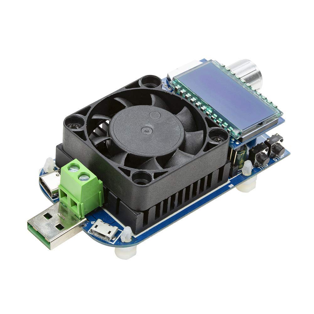
Figure 1.1: UCTRONICS Electronic USB Load Tester, showcasing its compact design with an integrated cooling fan and LCD display.
2. Key Components and Interfaces
Familiarize yourself with the main components and connection interfaces of the USB Load Tester:

Figure 2.1: Labeled diagram of the USB Load Tester, highlighting its key components.
- USB Male Port: Standard USB-A connector for direct connection to USB power sources.
- 마이크로 USB 포트: Input port for connecting devices via Micro USB cable.
- C 형 포트 : Input port for connecting devices via USB Type-C cable.
- Screw Terminal Blocks: External wiring ports for connecting power sources that do not use standard USB connectors.
- Intelligent Temperature-Controlled Heatsink with Cooling Fan: Dissipates heat generated during discharge, ensuring stable operation and preventing overheating.
- LCD 디스플레이: 실시간 볼륨을 보여줍니다tage, current, power, capacity (Ah), energy (Wh), and elapsed time.
- 인코더 손잡이: Used to navigate menus, adjust current values, and select modes. It can also be pressed for confirmation.
- "TRG" (Trigger) Button: Initiates fast charge protocol detection or mode selection.
- "STOP" (ON/OFF) Button: Functions as an ON/OFF switch for the discharge process.

그림 2.2: 상세 view of the Type-C and Micro USB input ports.

그림 2.3: 밑면 view of the module, revealing the printed circuit board (PCB) and components.
3. 설정 및 초기 작동
- 전원 켜기: Connect the USB Load Tester to a USB power source (e.g., charger, power bank) using the appropriate input port (USB-A male, Micro USB, Type-C, or screw terminals). The LCD display will light up, indicating the device is powered on.
- 초기 표시: Upon power-on, the display will typically show the input voltage and a flashing current value (e.g., "0.00A" or a previously set value). A flashing current value indicates that the module is in an "off" state and not actively discharging current.
4. 사용 설명서
4.1. Testing Quick Charge Protocols
To determine the fast charge protocols supported by a charger and trigger specific voltag에스:
- Connect the charger to the USB Load Tester using any of its input ports.
- Press and hold the "TRG" (Trigger) button for a few seconds. The module will begin communicating with the charger to identify compatible fast charge protocols (e.g., QC2.0, QC3.0, AFC, FCP).
- The LCD will cycle through the detected protocols and their corresponding voltages (e.g., 5V, 9V, 12V, 20V).
- To manually select a compatible mode, briefly press the "TRG" button. Then, rotate the encoder knob to cycle through the available modes. Press the encoder knob to confirm your selection. The module will then attempt to trigger that specific voltag전자 충전기에서.
4.2. Performing Load Tests (Discharge)
To perform a constant current discharge test on a power source:
- Ensure the module is connected to the power source you wish to test. The current value on the LCD should be flashing, indicating it's in the "off" state.
- Rotate the encoder knob to adjust the desired discharge current. The current value will change on the display.
- Once the desired current is set, press the "STOP" (ON/OFF) button. The current value will stop flashing, and the module will begin discharging at the set current. The fan will activate if necessary to maintain temperature.
- During discharge, the LCD will display real-time voltage and current. Press the encoder knob briefly to cycle through other displayed metrics:
- 전력(W): Instantaneous power consumption.
- 용량(Ah): Accumulated charge discharged in Amp영업시간 전.
- 에너지(Wh): Accumulated energy discharged in Watt-hours.
- Elapsed Time (h): Duration of the discharge test.
- To stop the discharge, press the "STOP" (ON/OFF) button again. The current value will start flashing, indicating the discharge has ceased.
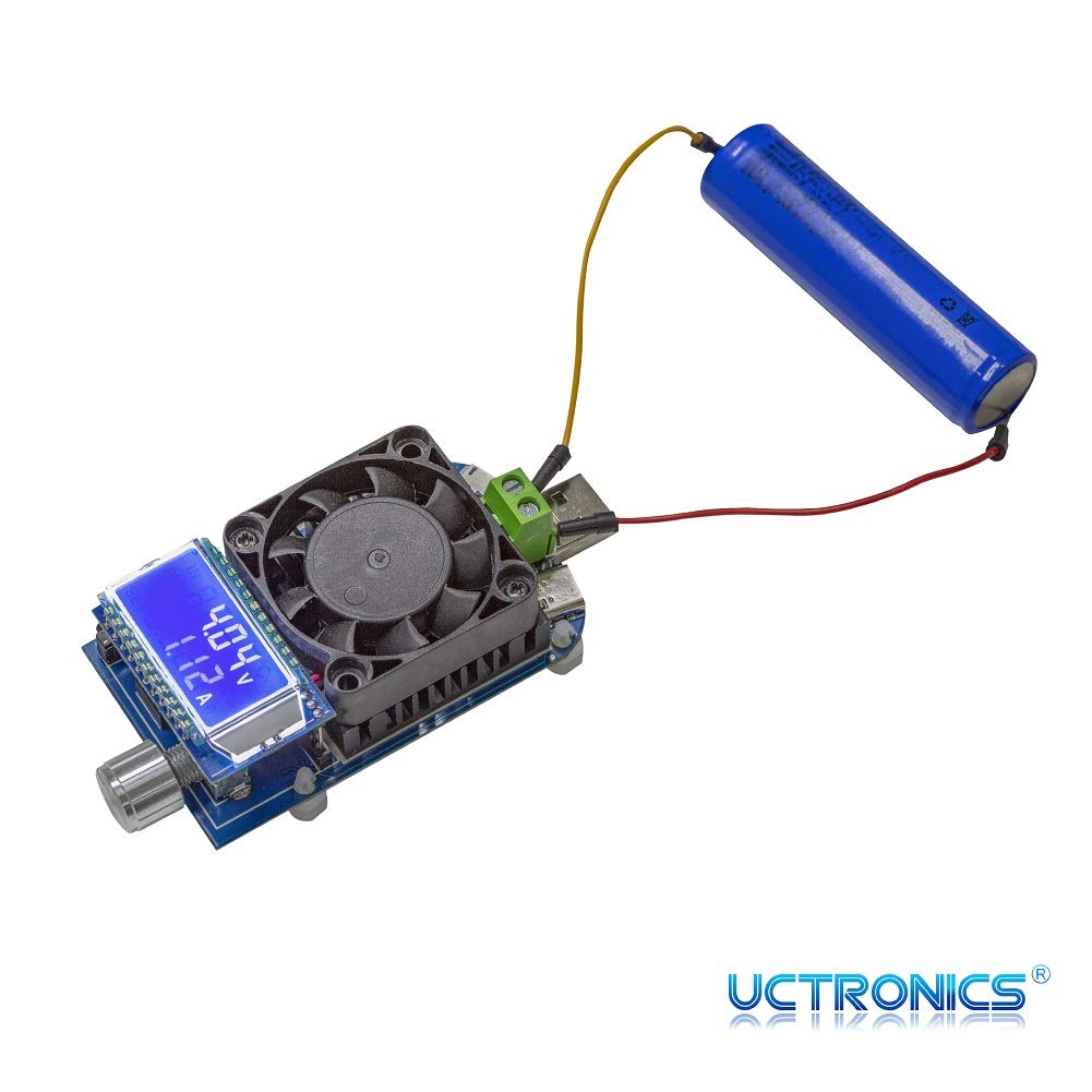
Figure 4.1: The load tester connected to a battery, demonstrating its use in discharge testing.
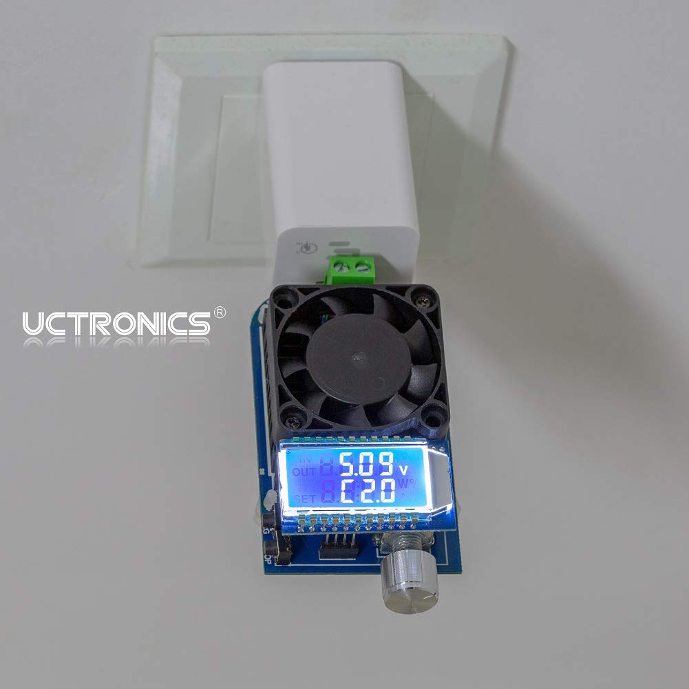
Figure 4.2: The load tester connected to a wall charger, used for evaluating charger performance.
5. 안전 기능 및 보호 장치
The UCTRONICS USB Load Tester incorporates several safety mechanisms to protect both the device and the connected power source:
- Anti-Reverse Protection: Prevents damage if the input polarity is accidentally reversed.
- 오버볼tag전자 보호(OVP): Automatically stops discharge if the input voltage exceeds a safe limit (adjustable).
- 과전류 보호(OCP): Stops discharge if the current draw exceeds the set maximum.
- Over-Power Protection (OPP): Stops discharge if the power consumption exceeds the maximum rated power (35W, adjustable).
- 저용량tage 보호(LVP): Stops discharge if the input voltage drops below a critical threshold, protecting the power source from deep discharge.
- Over-Temperature Protection (OTP): The intelligent cooling fan and internal circuitry prevent the device from overheating during prolonged use.
These protection limits can often be adjusted via the device's menu. To access and adjust these settings, refer to the device's on-screen menu by pressing and holding the encoder knob. The display will show options like OVP, OHP (Over-Hour Protection), OAH (Over-Ampere-Hour Protection), and OPP.

Figure 5.1: The LCD display showing adjustable protection settings for safe operation.
6. 문제 해결
- 장치 전원이 켜지지 않음:
Ensure the power source is active and providing sufficient voltage (DC 4.0-25.0V). Check all cable connections for proper seating. Try a different power source or cable.
- Current Setting Stuck/Cannot Adjust:
If the current setting is unresponsive, try disconnecting and reconnecting the power. Ensure the device is in the "off" state (flashing current value) before attempting to adjust the current with the encoder knob. If the issue persists, a factory reset might be needed (refer to advanced settings if available, or contact support).
- "OPP" Flashing on Display:
This indicates Over-Power Protection has been triggered. The current power draw (Voltage x Current) exceeds the set OPP limit. Reduce the discharge current or adjust the OPP setting if appropriate for your test setup.
- 팬이 회전하지 않음:
The fan is temperature-controlled and will only activate when the heatsink reaches a certain temperature during discharge. If the fan does not spin even under high load, ensure there are no obstructions and contact support if necessary.
- 부정확한 판독:
Ensure connections are secure and clean. For cable quality testing, note that a significant voltage drop indicates a lower quality cable. Compare readings with a calibrated multimeter if precision is critical.
7. 유지관리
To ensure the longevity and optimal performance of your UCTRONICS USB Load Tester:
- 청소: Use a soft, dry cloth to clean the device. Avoid using liquids or abrasive cleaners. Ensure the fan and heatsink fins are free from dust and debris for efficient cooling.
- 저장: 본 기기는 직사광선과 극한의 온도를 피해 시원하고 건조한 곳에 보관하세요.
- 손질: Handle the device with care. Avoid dropping it or subjecting it to strong impacts, as this can damage internal components or the LCD screen.
8. 사양
| 특징 | 사양 |
|---|---|
| 모델 번호 | RS2818 |
| 상표 | 유크로닉스 |
| 정격 운영 볼륨tage | DC 4.0-25.0V |
| 최대 방전 전력 | 35와트 |
| 정격 작동 전류 | 0.03-5.00A |
| 지원되는 고속 충전 프로토콜 | QC2.0, QC3.0, AFC, FCP |
| 트리거 출력 볼륨tages | 5V, 9V, 12V, 20V |
| 연결 포트 | USB-A Male, Micro USB, Type-C, External Wiring Port |
| 냉각 | Intelligent Temperature Control with Cooling Fan |
| 안전 보호 | Anti-reverse, OVP, OCP, OPP, LVP, OTP |
| 패키지 크기 | 4.5 x 2.5 x 1.5 인치 |
| 품목 무게 | 3.21 온스 |
| 원산지 | 중국 |
9. 보증 및 지원
UCTRONICS products are designed for reliability and performance. For any technical assistance, troubleshooting, or warranty inquiries, please contact UCTRONICS customer support through their official channels. Please retain your proof of purchase for warranty claims.
For more information and support, visit the official UCTRONICS web사이트 또는 고객 서비스 부서에 문의하십시오.


