1. 소개 및 제품 끝view
This manual provides detailed instructions for the installation, operation, and maintenance of your American Volt Universal Electric Radiator Cooling Fan Thermostat Temp Sensor Switch. This product is designed to automatically control electric cooling fans in automotive applications based on engine or fluid temperature.
The kit includes two temperature sensor switches, each featuring a brass thread-in probe compatible with 3/8" and 1/2" NPT threaded ports. The switch is engineered to activate (ground) the cooling fan when the temperature reaches 180°F and deactivate it when the temperature drops to 165°F, ensuring optimal engine cooling.

Image 1.1: Two American Volt Universal Electric Radiator Cooling Fan Thermostat Temp Sensor Switches. These are the primary components of the product, showing their brass construction and electrical terminals.
2. 제품 특징
- 듀얼 팩: Includes two automotive engine grounding fan temperature switches.
- Temperature Activation: Grounds the fan at 180°F and turns off at 165°F.
- Versatile Probe: Brass thread-in temperature probe with 3/8" and 1/2" NPT adapter.
- 범용 적용: Suitable for any application with a 1/2" NPT threaded port.
- 유연한 장착: Threads into engine block, radiator, manifold, water outlet, or other suitable locations.
- 유체 호환성: Capable of measuring the temperature of various liquids, including motor oil.
- Included Connectors: Comes with 2 insulated female wire connectors for ease of installation.

이미지 2.1: 상세 view of a single American Volt temperature sensor switch. This image highlights the brass probe and the threaded body, which allows for secure installation into various automotive components.
3. 사양
| 사양 | 값 |
|---|---|
| 작동 모드 | 오토매틱 |
| 운영 볼륨tage | 12볼트(DC) |
| 연락처 유형 | 일반적으로 오픈 |
| 커넥터 유형 | 나사 |
| 단말기 | 나사 |
| 회로 유형 | 1방향 |
| 장착 유형 | 나사산 마운트 |
| 접촉 재료 | 놋쇠 |
| 국제 보호 등급 | IP00 |
| 위치 수 | 2 |
| Lower Temperature Rating (Turn-Off) | 화씨 165도 |
| Upper Temperature Rating (Turn-On) | 화씨 180도 |
| 단위 수 | 2.0 카운트 |
| 제조업체 부품 번호 | AV-1022 |
4. 설정 및 설치
Proper installation is crucial for the correct operation of the temperature sensor switch. Always disconnect the vehicle's battery before beginning any electrical work.
4.1. 설치 위치 선택
The sensor can be threaded into any suitable 1/2" NPT port that accurately reflects the temperature of the fluid you wish to monitor. Common locations include:
- 엔진 블록
- Radiator (in-tank or hose adapter)
- 흡기 다기관
- 물 배출구
Ensure the chosen location allows the brass probe to be fully immersed in the fluid for accurate temperature readings. If your port is 3/8" NPT, use the provided adapter.

Image 4.1: NPT - American Standard Pipe Thread/Taper Guide. This guide helps in identifying the correct NPT size for your application, ensuring a proper fit for the sensor switch.
4.2. 기계적 설치
- Ensure the engine and cooling system are cool to prevent burns.
- Drain a small amount of coolant if installing directly into the cooling system to prevent spills.
- Apply a suitable thread sealant (e.g., PTFE tape or liquid thread sealant) to the threads of the sensor probe.
- Carefully thread the sensor into the chosen port. Do not overtighten, as this can damage the sensor or the port. Tighten until snug and leak-free.
- Refill any drained coolant and check for leaks.
4.3. 전기 배선
The sensor switch operates by providing a ground signal to activate a relay, which in turn powers the electric cooling fan. Refer to the wiring diagram below for proper connections.
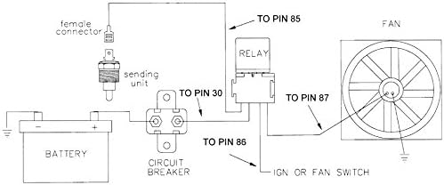
Image 4.2: Typical Wiring Diagram for Electric Cooling Fan Thermostat Switch. This diagram illustrates how to connect the temperature sensor switch to a relay, circuit breaker, battery, and the electric fan for automatic operation.
- 센서에 연결: Use the provided insulated female wire connectors to attach a wire to the single terminal on the temperature sensor switch.
- Connect to Relay: Connect the other end of this wire to the appropriate terminal on your fan relay (typically pin 85 or the coil ground terminal).
- Power and Fan Connections: Follow the relay manufacturer's instructions for connecting the relay to the battery (via a circuit breaker), ignition/fan switch (if applicable), and the electric cooling fan. Ensure all connections are secure and properly insulated.
- 접지: Ensure the fan and battery have proper chassis grounds. The sensor switch provides a ground signal to the relay.
중요한: Always use an appropriately rated circuit breaker or fuse in the main power line to protect the circuit.
5. 사용 설명서
Once properly installed and wired, the American Volt temperature sensor switch operates automatically. There are no user-adjustable settings.
- When the fluid temperature reaches approximately 화씨 180도(섭씨 82도), the sensor switch will close its internal contacts, providing a ground signal to the connected relay. This will activate the electric cooling fan.
- The cooling fan will continue to run until the fluid temperature drops to approximately 화씨 165도(섭씨 74도). At this point, the sensor switch will open its contacts, interrupting the ground signal and deactivating the cooling fan.
This cycle will repeat as necessary to maintain the desired operating temperature range for your cooling system.
6. 유지관리
The American Volt temperature sensor switch is designed for long-term, maintenance-free operation. However, periodic checks can help ensure continued reliability:
- 시각적 검사: Periodically inspect the sensor and its wiring for any signs of corrosion, damage, or loose connections.
- 유체 누출: Check around the sensor's threaded connection for any signs of coolant or fluid leaks. Tighten if necessary, but do not overtighten.
- 전기 연결: Ensure the female wire connector remains securely attached to the sensor terminal.
- 청결: Keep the sensor and surrounding area free of excessive dirt, grease, or debris.
7. 문제 해결
If your electric cooling fan is not operating as expected with the temperature sensor switch, consider the following troubleshooting steps:
| 문제 | 가능한 원인 | 해결책 |
|---|---|---|
| Fan does not turn on at 180°F | No power to relay; Faulty relay; Open circuit in wiring; Sensor not reaching temperature; Faulty sensor | Check circuit breaker/fuse; Test relay operation; Inspect all wiring connections (refer to Image 4.2); Verify engine/fluid temperature with a separate gauge; Test sensor continuity (should show continuity when hot); Replace faulty component. |
| 팬이 계속 작동합니다. | Sensor stuck closed (grounded); Wiring shorted to ground; Faulty relay | Disconnect sensor wire from relay; if fan stops, sensor is faulty. If fan continues, check wiring for shorts or replace relay. |
| 부정확한 온도 판독값 | Sensor not fully immersed in fluid; Air pocket around sensor; Incorrect sensor type | Ensure sensor probe is fully submerged; Bleed cooling system to remove air; Verify correct sensor for application. |
| Fluid leaks around sensor | Insufficient thread sealant; Overtightened/damaged threads | Remove, reapply thread sealant, and reinstall; Inspect threads for damage; Replace sensor or port if threads are stripped. |
문제 해결 단계를 수행해도 문제가 해결되지 않으면 자격을 갖춘 자동차 기술자에게 문의하는 것이 좋습니다.
8. 보증 정보
Specific warranty details for American Volt products are typically provided at the point of purchase or on the manufacturer's official website. Please retain your proof of purchase for any warranty claims. For the most current and detailed warranty information, please refer to the American Volt official web사이트를 방문하거나 고객 지원팀에 직접 문의하세요.
9. 지원
For technical assistance, product inquiries, or support, please contact American Volt customer service. Visit the official American Volt web연락처 정보, FAQ 및 추가 리소스를 제공하는 사이트입니다.
American Volt Store: Visit the American Volt Store on Amazon


