1. 서론
This manual provides detailed instructions for the installation, operation, and maintenance of your Foxconn TSAA725 ATX Tower Case. Please read this manual thoroughly before beginning installation to ensure proper setup and safe use of the product. Keep this manual for future reference.
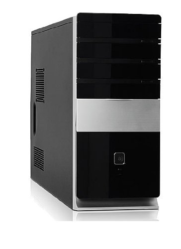
이미지: 앞면 view of the Foxconn TSAA725 ATX Tower Case, showcasing its design and front panel ports.
2. 안전 정보
제품 손상이나 부상 방지를 위해 다음 안전 예방 조치를 준수하세요.
- Always disconnect the power supply from the wall outlet before opening the computer case or performing any installation/maintenance.
- Handle internal components with care to avoid electrostatic discharge (ESD) damage. Use an anti-static wrist strap if available.
- 과열을 방지하려면 케이스 주변의 적절한 환기를 확보하세요.
- 케이스를 습기나 극한 온도에 노출시키지 마십시오.
- 작은 부품은 어린이의 손이 닿지 않는 곳에 보관하세요.
3. 패키지 내용
패키지에 모든 품목이 들어 있는지 확인하세요.
- Foxconn TSAA725 ATX Tower Case
- 350W 전원 공급 장치(사전 설치됨)
- Accessory kit (screws, standoffs, cable ties)
- 이 사용 설명서
4. 주요 특징
The Foxconn TSAA725 ATX Tower Case offers the following features:
- 재료: 0.5mm SGCC Alloy Steel construction for durability.
- 마더보드 지원: Compatible with ATX and Micro ATX motherboards.
- 드라이브 베이 :
- 3x 5.25" External Bays
- 2x 3.5" External Bays
- 4x 3.5" Internal Bays
- 냉각 시스템:
- 1x 80/92/120mm rear fan support (fan not included)
- Optional 1x 80/92/120mm front fan support (fan not included)
- 80mm Air Duct for CPU cooling.
- 전면 I/O 패널:
- 2x USB 2.0 포트
- 1x 헤드폰 잭
- 마이크 잭 1개
- 전원 공급 장치: Integrated 350W Power Supply.
5. 설정 및 구성 요소 설치
Follow these steps to install your computer components into the Foxconn TSAA725 case:
- 사례 준비:
Place the case on a flat, stable surface. Remove the side panel(s) by unscrewing the thumbscrews at the rear of the case and sliding the panel backward.
- 마더보드 설치:
Install the necessary standoffs onto the motherboard tray according to your motherboard's form factor (ATX or Micro ATX). Carefully place the motherboard onto the standoffs, aligning the screw holes. Secure the motherboard with screws provided in the accessory kit.
- Install Drives (HDD/SSD):
For 3.5" internal drives, slide the drive into an available 3.5" internal bay and secure it with screws from the side. For 5.25" external drives (e.g., optical drives), remove the front panel bay cover, slide the drive in from the front, and secure it with screws.
- 확장 카드 설치:
Remove the appropriate expansion slot covers at the rear of the case. Insert your graphics card or other expansion cards into the PCIe/PCI slots on the motherboard and secure them with screws.
- 케이블 연결:
Connect the power supply cables to the motherboard (24-pin ATX, 4/8-pin CPU), graphics card (if applicable), and drives (SATA power). Connect the front panel cables (USB, audio, power switch, reset switch, LED indicators) to the corresponding headers on the motherboard. Refer to your motherboard manual for header locations.
- 케이블 관리 :
Route cables neatly to improve airflow and aesthetics. Use cable ties from the accessory kit if needed.
- 사건 종결:
Once all components are installed and cables are connected, reattach the side panel(s) and secure them with the thumbscrews.
6. 사용 설명서
After successful assembly, connect your peripherals (monitor, keyboard, mouse) and power cable to the case. Press the power button on the front panel to start your computer.
전면 패널 I/O 포트:
- USB 2.0 포트: 키보드, 마우스, 외장 저장 장치 등의 USB 장치를 연결하는 데 사용합니다.
- 헤드폰 잭: 헤드폰이나 스피커를 연결합니다.
- 마이크 잭 : 마이크를 연결합니다.
- 전원 버튼: 컴퓨터를 켜거나 끕니다.
- 재설정 버튼: To restart the computer.
7. 유지관리
Regular maintenance helps ensure optimal performance and longevity of your computer case:
- 먼지 청소: Periodically clean dust from inside the case, especially from fans and heatsinks, using compressed air. Ensure the computer is powered off and unplugged before cleaning.
- 외부 청소: 케이스 외부를 부드러운 천으로 닦아주세요.amp 천으로 닦으세요. 연마성 세제나 용제는 사용하지 마세요.
- 케이블 관리 : 케이블이 공기 흐름이나 팬 작동을 방해하지 않도록 주기적으로 케이블 배선을 점검하십시오.
8. 문제 해결
문제가 발생하면 다음의 일반적인 해결책을 참조하세요.
- 컴퓨터 전원이 켜지지 않습니다:
- Ensure the power cable is securely connected to both the case's power supply and the wall outlet.
- Check if the power supply switch (if present) is in the 'ON' position.
- 전면 패널 전원 버튼 케이블이 마더보드에 올바르게 연결되어 있는지 확인하십시오.
- 모니터에 아무것도 표시되지 않음:
- Ensure the monitor is powered on and connected to the correct video output on your graphics card or motherboard.
- 그래픽 카드와 RAM 모듈을 다시 장착하세요.
- USB 포트가 작동하지 않습니다.
- 전면 패널 USB 케이블이 마더보드의 USB 헤더에 올바르게 연결되어 있는지 확인하십시오.
- 장치를 다른 USB 포트에 연결해 보세요.
9. 사양
| 특징 | 세부 사항 |
|---|---|
| 상표 | 폭스콘 |
| 모델 | TSAA725-ISO450 |
| 재료 | 0.5mm SGCC Alloy Steel |
| 마더보드 호환성 | ATX, 마이크로 ATX |
| Drive Bays (External) | 3개 5.25인치, 2개 3.5인치 |
| Drive Bays (Internal) | 4x 3.5" |
| 냉각 시스템 지원 | 1x 80/92/120mm rear fan, 1x 80/92/120mm front fan (optional), 80mm Air Duct |
| 전면 I / O 포트 | 2x USB 2.0, 1x Headphone, 1x Microphone |
| 전원 공급 장치 | 350W (Integrated) |
| 제품 크기(LxWxH) | 50.17 x 24.13 x 54.61cm |
| 품목 무게 | 6.96kg |
10. 보증 및 지원
For warranty information and technical support, please refer to the official Foxconn web사이트를 방문하거나 가까운 판매점에 문의하세요. 보증 청구를 위해 구매 증빙 자료를 보관하세요.
온라인 리소스: For additional support and updated drivers, visit the official Foxconn support page.
참고: 보증 조건은 지역에 따라 다를 수 있습니다.


