1. 서론
This manual provides essential information for the installation, operation, and maintenance of the JOCCOS FX3U-24MR and FX3U-24MT series Programmable Logic Controllers (PLCs). These devices are designed for industrial control applications, offering robust performance and versatile connectivity. Please read this manual thoroughly before using the product to ensure safe and correct operation.
2. 안전 정보
신체 부상이나 장비 손상을 방지하려면 항상 다음 안전 예방 조치를 준수하세요.
- 배선 작업이나 유지 보수 작업을 하기 전에 반드시 전원을 차단하십시오.
- 자격을 갖춘 인력만이 이 장비를 설치, 작동, 유지관리해야 합니다.
- PLC를 지정된 온도, 습도 또는 진동 한계를 초과하는 환경에서 작동하지 마십시오.
- Ground the PLC properly to prevent electrical shock and ensure stable operation.
- 전원을 공급하기 전에 모든 배선 연결이 안전하고 올바른지 확인하세요.
3. 제품 오버view
The JOCCOS FX3U-24MR and FX3U-24MT PLCs are compact industrial control boards featuring a range of digital and analog I/O, along with communication interfaces.
3.1. 주요 특징
- 디지털 I/O: 14 Digital Inputs (DI) / 10 Digital Outputs (DO)
- 아날로그 입출력: 6 Analog Inputs (AI) / 2 Analog Outputs (AO)
- 의사소통: RS232 and RS485 ports
- 모델: FX3U-24MR (Relay Output), FX3U-24MT (Transistor Output)
3.2. Component Identification (FX3U-24MR)
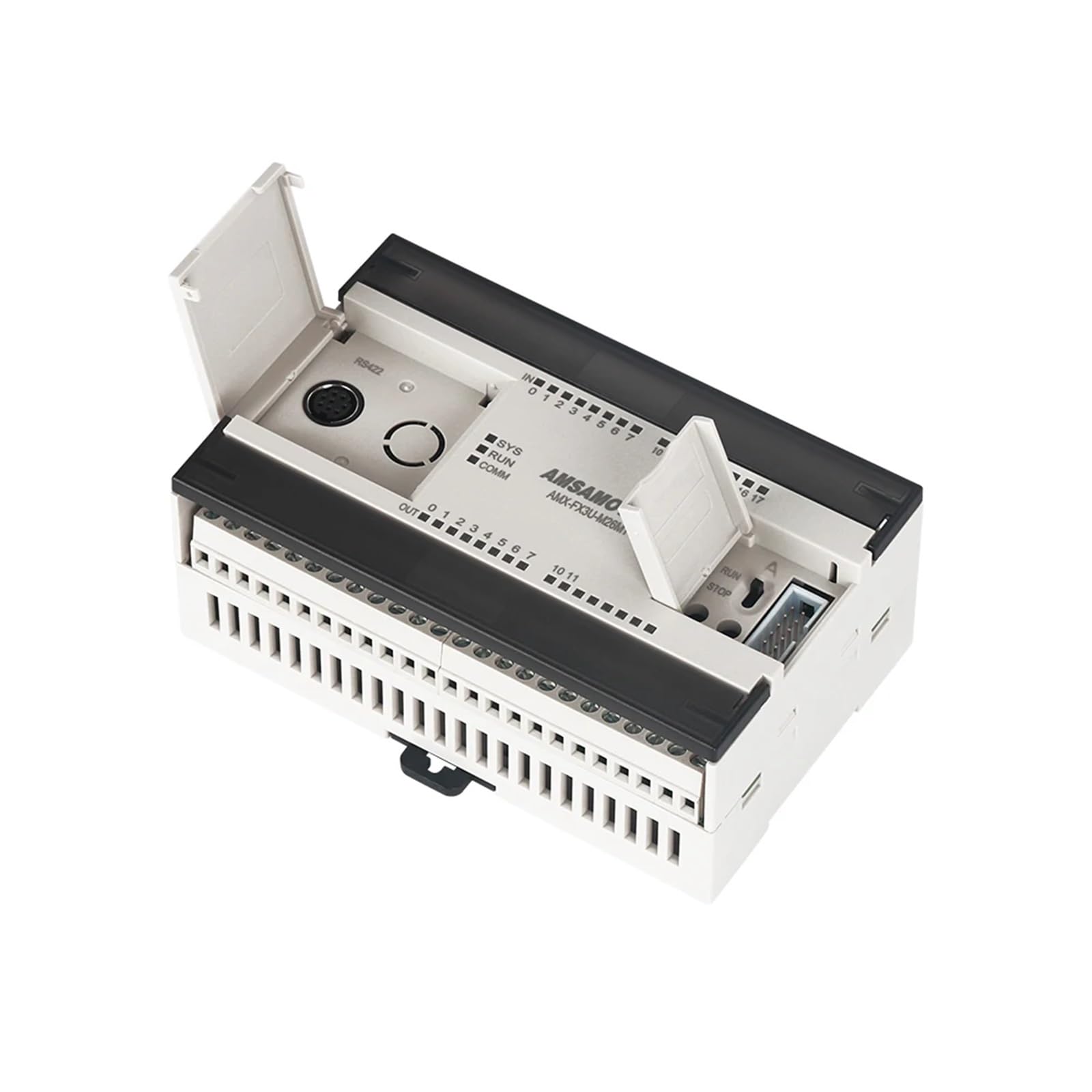
그림 1: 상단 view of the JOCCOS FX3U-24MR PLC. This image displays the green terminal blocks for digital inputs (top) and digital outputs (bottom right), the blue DB9 RS232 serial port (bottom left), and the internal circuit board with various electronic components visible through the transparent casing.
3.3. Component Identification (FX3U-24MT)
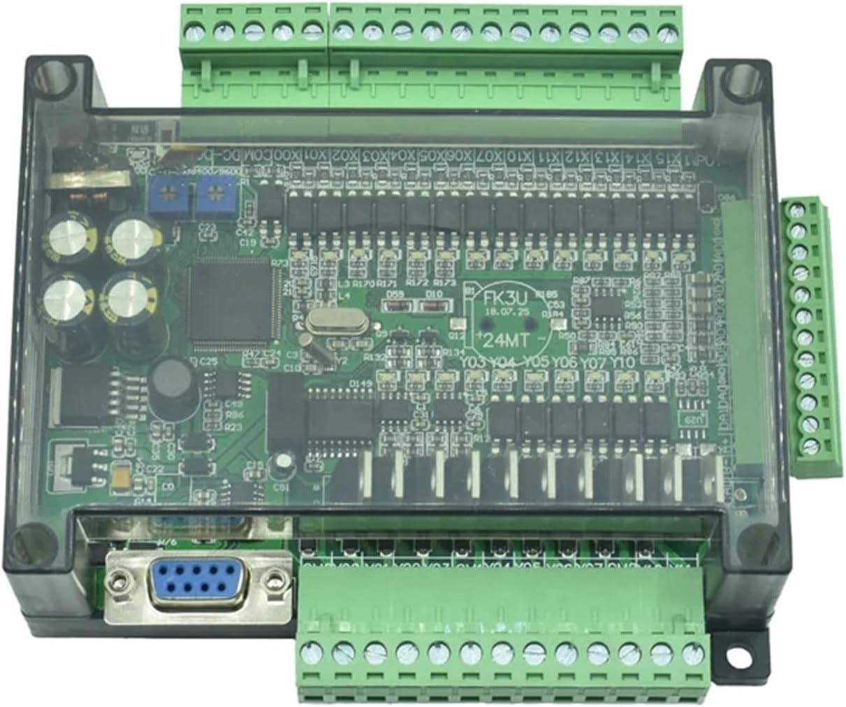
그림 2: 상단 view of the JOCCOS FX3U-24MT PLC. Similar to the MR model, this image highlights the green terminal blocks for digital inputs and outputs, the DB9 RS232 port, and the internal components, specifically indicating the transistor output type.
4. 사양
| 특징 | 사양 |
|---|---|
| 디지털 입력(DI) | 14 |
| 디지털 출력(DO) | 10 (MR: Relay, MT: Transistor) |
| 아날로그 입력(AI) | 6 |
| 아날로그 출력(AO) | 2 |
| 통신 포트 | RS232, RS485 |
| 전원 공급 장치 | DC 24V (typical) |
| 품목 무게 | 50그램(1.76온스) |
| 패키지 크기 | 1.18 x 0.79 x 0.39 인치 |
| 제조업체 | JOCCOS |
| 모델 번호 | JOCCOS (Generic, refer to FX3U-24MR/MT for specific model) |
5. 설정
5.1. 장착
The PLC is designed for panel mounting. Use appropriate screws to secure the unit to a stable surface. Ensure adequate ventilation around the unit to prevent overheating.
5.2. 배선
All wiring should be performed with power disconnected. Use appropriate wire gauges for power and signal connections. Refer to the terminal labels on the PLC for correct connections.
- 전원 공급 장치: Connect a stable DC 24V power source to the designated power terminals. Observe polarity.
- 디지털 입력 : Connect sensors, switches, or other input devices to the DI terminals (X0-X13).
- 디지털 출력 : Connect actuators, relays, or other output devices to the DO terminals (Y0-Y9). Ensure the load current does not exceed the specified limits for relay (MR) or transistor (MT) outputs.
- 아날로그 입력 : Connect analog sensors (e.g., 0-10V, 4-20mA) to the AI terminals.
- 아날로그 출력: Connect analog actuators or drives to the AO terminals.
- 통신 포트: Use standard RS232 or RS485 cables to connect to programming devices or other communication modules.

그림 3: 각도 view of the JOCCOS FX3U-24MR PLC, illustrating the accessible terminal blocks for wiring. This perspective helps in identifying the connection points for power, digital inputs, digital outputs, analog signals, and communication interfaces.
6. 사용 설명서
6.1. 소프트웨어 프로그래밍
The JOCCOS FX3U series PLCs are compatible with standard Mitsubishi FX series programming software, such as GX Works2 or GX Developer. Install the software on your computer and ensure proper communication drivers are installed.
6.2. 커뮤니케이션 구축
Connect the PLC to your computer using an RS232 or RS485 programming cable. Configure the communication settings in the programming software to match the PLC's default or configured settings (e.g., baud rate, data bits, stop bits, parity).
6.3. Program Download and Upload
- 다운로드: After creating your ladder logic program, compile it and download it to the PLC's memory. Ensure the PLC is in STOP mode before downloading.
- 업로드: You can upload the existing program from the PLC to your computer for backup or modification.
6.4. Run/Stop Mode
The PLC can be switched between RUN and STOP modes via the programming software. In RUN mode, the PLC executes the loaded program. In STOP mode, the program execution is halted, allowing for program changes or debugging.
7. 유지관리
7.1. 청소
Periodically clean the PLC's exterior with a soft, dry cloth. Do not use solvents or abrasive cleaners. Ensure no dust or debris accumulates in the ventilation openings.
7.2. 펌웨어 업데이트
제조사 확인해보세요 website for any available firmware updates. Follow the provided instructions carefully when performing updates to avoid damaging the unit.
7.3. 배터리 교체 (해당되는 경우)
Some PLC models may include a battery for retaining program data or real-time clock settings. If your model has a battery, refer to specific instructions for replacement to avoid data loss.
8. 문제 해결
이 섹션에서는 일반적으로 발생할 수 있는 문제에 대해 설명합니다.
| 문제 | 가능한 원인 | 해결책 |
|---|---|---|
| PLC not powering on | No power supply, incorrect wiring, faulty power supply | Check power connections, verify DC 24V supply, test power supply unit. |
| PC와 통신할 수 없습니다. | Incorrect cable, wrong communication settings, driver issues | Ensure correct RS232/RS485 cable, match baud rate/settings in software, reinstall communication drivers. |
| 디지털 입력이 응답하지 않습니다 | Sensor faulty, incorrect wiring, input not configured in program | Check sensor operation, verify input wiring, confirm input address in PLC program. |
| Digital output not activating | Actuator faulty, incorrect wiring, output not configured in program, overload | Check actuator, verify output wiring, confirm output address in PLC program, check for overcurrent. |
| 아날로그 입력 판독 오류 | Sensor faulty, incorrect wiring, scaling issues in program | Verify sensor output, check analog input wiring, review scaling parameters in PLC program. |
9. 보증 및 지원
JOCCOS products are manufactured to high-quality standards. For warranty information, please refer to the terms and conditions provided at the time of purchase or contact your vendor. For technical support, please reach out to your supplier or the JOCCOS customer service department with your product model and purchase details.