
1. 서론
The diymore LCR-TC1 is a versatile multi-function transistor tester designed for automatic detection and measurement of various electronic components. This device can identify NPN and PNP transistors, N-channel and P-channel MOSFETs, diodes (including double diodes), thyristors, resistors, capacitors, and inductors. It features a full-color display for clear readings and is powered by a built-in lithium battery for convenience. This manual provides detailed instructions for the safe and effective use of your LCR-TC1 tester.
2. 안전 정보
- Always ensure the component under test is fully discharged before connecting it to the tester, especially capacitors. Failure to do so can damage the tester.
- 충전 입력 볼륨tage is 4.5V. Do not use an over-voltage charger, as this will damage the tester's internal circuitry.
- Do not attempt to test components while they are connected to a live circuit.
- 장치를 물과 극한의 온도에서 멀리하세요.
- c를 열지 마세요asing of the device unless you are a qualified technician.
3. 제품 오버view
The diymore LCR-TC1 Multi-Function Tester is equipped with a clear display and intuitive controls for easy operation. Below is an illustration of the main components and their functions.

그림 3.1: LCR-TC1 Tester with labeled parts including 160x128 TFT display, IR receiver window, multi-function key, Start button, transistor test area, Zener diode test area, Micro USB charging interface, and charge indicator LED.
- 160x128 TFT Display: Shows test results and device status.
- IR 수신기 창: Used for decoding Hitachi-style IR remote control signals.
- 다기능 키: For navigating menus or selecting options (if applicable).
- 시작 버튼: Initiates the component test.
- Transistor Test Area: ZIF (Zero Insertion Force) socket for connecting components with multiple pins (e.g., transistors, ICs). Numbered pins (1, 2, 3) correspond to test points.
- Zener Diode Test Area: Dedicated area for testing Zener diodes.
- Micro USB Charging Interface: 내부 리튬 배터리를 충전합니다.
- 충전 표시기 LED: 배터리가 완전히 충전되면 녹색으로 켜집니다.
4. 사양
The following table outlines the key performance parameters and general specifications of the diymore LCR-TC1 Multi-Function Transistor Tester.
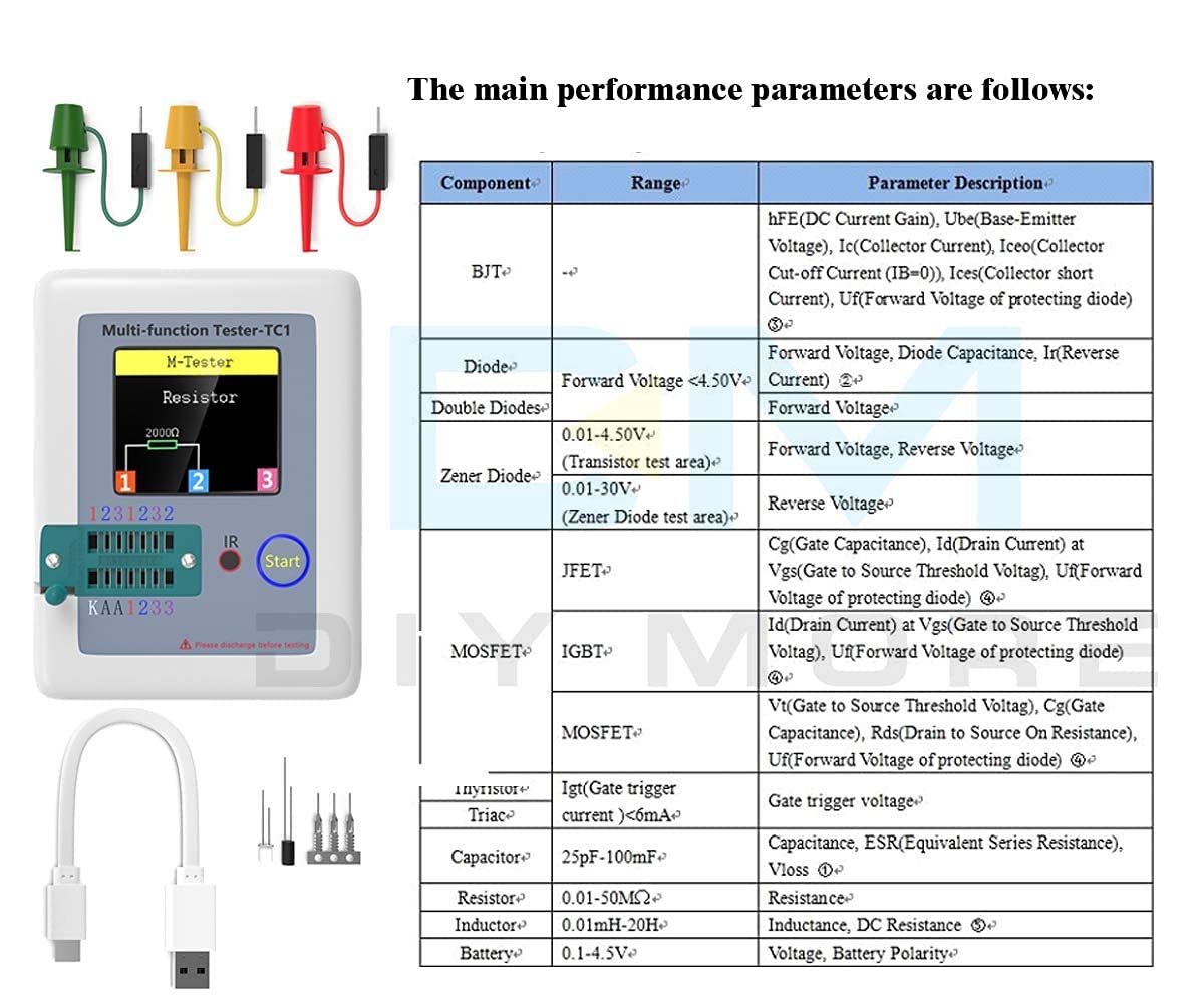
그림 4.1: Main performance parameters including component types (BJT, Diode, Double Diodes, Zener Diode, JFET, MOSFET, IGBT, Thyristor/Triac, Capacitor, Resistor, Inductor, Battery) and their respective measurement ranges and parameter descriptions.
| 매개변수 | 값 |
|---|---|
| 상표 | DIY모어 |
| 모델 번호 | LCR-TC1 |
| 전원 | 배터리 구동식 (내장 리튬 배터리) |
| 최소 작동 볼륨tage | 4.5 Volts (Charging Input) |
| 최대 작동 볼륨tage | 4.5 Volts (Charging Input) |
| 측정 유형 | LCR 미터 |
| 품목 무게 | 0.12 킬로그램 |
| 원산지 | 중국 |
| 포함된 구성 요소 | Transistor Meter |
5. 설정
Before using your LCR-TC1 tester for the first time, ensure it is adequately charged.
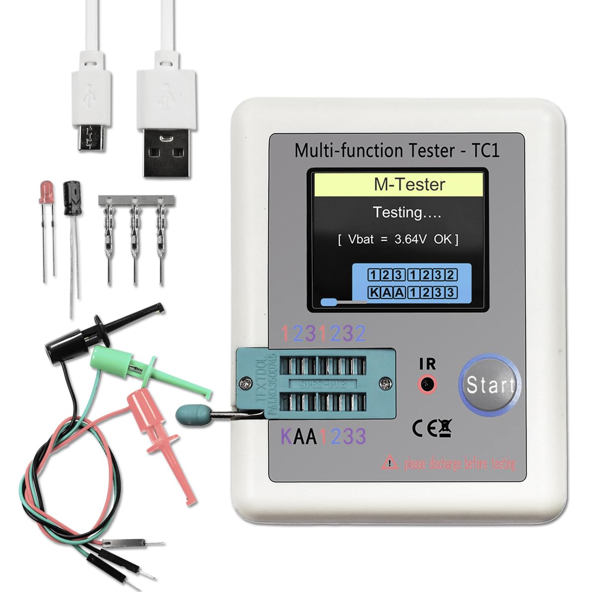
그림 5.1: LCR-TC1 tester shown with a Micro USB charging cable and various test clips, indicating readiness for use or charging.
- 배터리 충전: Connect the provided Micro USB cable to the charging interface on the tester and to a 4.5V USB power adapter (not included). The charge indicator LED will show the charging status. It will turn green when fully charged. Avoid using chargers with voltage 4.5V를 초과합니다.
- 초기 전원 켜기: Press the "Start" button to power on the device. The display will light up, and the tester will perform a self-check.
- 테스트 리드 연결: For components that cannot be inserted directly into the ZIF socket, use the included test clips. Connect the clips to the corresponding test points (1, 2, 3) on the tester.
6. 사용 설명서
The LCR-TC1 tester is designed for automatic component identification and measurement. Follow these steps for testing various components.
6.1. General Testing Procedure
- Ensure the component to be tested is discharged, especially capacitors.
- Connect the component to the tester. You can use the ZIF socket for multi-pin components or the test clips for others. Ensure good contact between the component leads and the test points (1, 2, or 3).
- Press the "Start" button. The tester will automatically identify the component type and measure its parameters.
- The results will be displayed on the TFT screen.
- The device has an automatic shutdown function to conserve battery. It will power off after approximately 20 seconds of inactivity.
6.2. Testing Specific Components

그림 6.1: Visual representation of the LCR-TC1 tester's capability to measure Inductance, Capacitance, Diode characteristics, and Resistance, showing typical component connections.
- 저항기: Connect the resistor leads to any two of the test points (1, 2, or 3). The tester will display the resistance value.
- 커패시터: Connect the capacitor leads to any two of the test points (1, 2, or 3). Ensure the capacitor is discharged before testing. The tester will display capacitance, ESR (Equivalent Series Resistance), and Vloss.
- 인덕터: Connect the inductor leads to any two of the test points (1, 2, or 3). The tester will display the inductance value and DC resistance.
- Diodes (including Double Diodes): Connect the diode leads to any two test points. The tester will identify the diode type and display forward voltage and reverse current.
- Transistors (NPN, PNP, MOSFET, JFET, IGBT): Insert the transistor leads into the ZIF socket, ensuring each lead (Emitter, Base, Collector for BJT; Source, Gate, Drain for FET) connects to a different test point (1, 2, or 3). The tester will identify the type, pinout, and measure parameters like hFE, Ube, Vt, Cgs, etc.

그림 6.2: A MOSFET connected to the LCR-TC1 tester using test clips, demonstrating how to test multi-pin components that may not fit the ZIF socket directly.
- Thyristors and Triacs: Connect the leads to test points. The tester will identify the component and its gate trigger current.
- Zener Diodes: Use the dedicated Zener diode test area for accurate measurements of Zener voltage.
- IR Remote Control Signals: Point a Hitachi-style IR remote control towards the IR receiver window and press a button. The tester will attempt to decode and display the signal.
7. 유지관리
- 청소: 테스터 외부를 닦을 때는 부드럽고 마른 천을 사용하십시오. 연마성 세제나 용제를 사용하지 마십시오.
- 저장: 본 기기는 직사광선과 극한의 온도를 피해 시원하고 건조한 곳에 보관하세요.
- 배터리 관리 : 기기를 자주 사용하지 않더라도 배터리 수명을 유지하려면 정기적으로 배터리를 충전하십시오. 배터리를 장시간 완전히 방전시키지 마십시오.
8. 문제 해결
| 문제 | 가능한 원인 | 해결책 |
|---|---|---|
| 장치의 전원이 켜지지 않습니다. | 배터리가 부족하거나 방전되었습니다. | Charge the device using a 4.5V Micro USB charger. |
| Incorrect or no reading displayed. | Poor connection to component; Component not discharged; Component is faulty. | Ensure component leads are clean and securely connected. Discharge capacitors before testing. Test a known good component to verify tester functionality. |
| Tester shuts off too quickly. | Automatic shutdown feature activated. | This is normal behavior to save battery. Press "Start" to reactivate. |
| 배터리가 충전되지 않습니다. | Aging battery; Incorrect charging voltage. | Ensure you are using a 4.5V charger. If the issue persists, the internal battery may need replacement by a qualified technician. |
9. 지원 및 보증
For any questions, technical assistance, or if you require further support regarding your diymore LCR-TC1 Multi-Function Transistor Tester, please contact the manufacturer or seller via email. Refer to your purchase documentation for specific contact details.
Regarding warranty, the product typically comes with a 10-day replacement policy. Please consult your retailer or purchase platform for the most accurate and up-to-date warranty information and terms of service.