
1. 서론
This manual provides detailed instructions for the DEVMO DC 5V/12V 1 Channel Relay Board, Model JZ801. This programmable multifunctional module is designed for various timing and control applications, offering flexible operation modes and robust performance.
주요 특징은 다음과 같습니다.
- 넓은 입력 voltage range: 6-30V, with micro USB 5.0V power supply option.
- Adjustable timing range: 0.1 seconds to 999 minutes.
- 높은 볼륨tage level trigger (3.0V-24V).
- Output capability: DC 0-30V 5A or AC 0-220V 5A.
- Opto-isolator for enhanced anti-interference.
- Reverse connect protection.
- Automatic parameter saving upon power-off.
- Sleep mode for power saving.
2. 패키지 내용
패키지에 모든 품목이 들어 있는지 확인하세요.
- 1x DEVMO 1 Channel Multi-functional Time Delay Relay Board (blue board)
- 1x USB to Micro USB Power Line
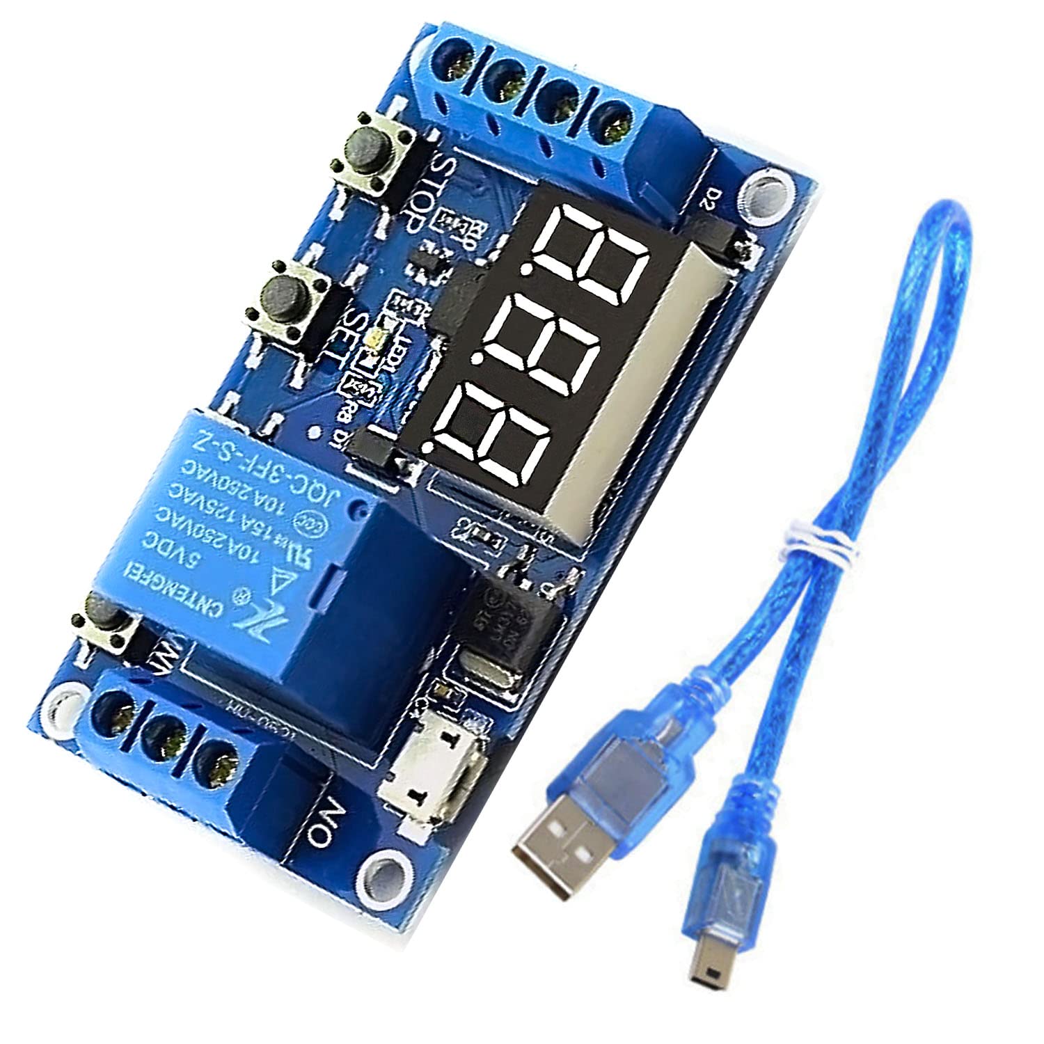
Figure 2.1: DEVMO JZ801 Relay Board and USB to Micro USB Power Line.
This image displays the DEVMO JZ801 1 Channel Relay Board, a blue circuit board with a 3-digit LED display, three control buttons (SET, STOP), a relay, and screw terminals for connections. A blue USB to Micro USB cable is also shown alongside the board.
3. 제품 오버view 및 연결
Familiarize yourself with the components and connection points of the relay board.

그림 3.1: 상단 view of the DEVMO JZ801 Relay Board.
이 이미지는 명확한 상향식을 제공합니다. view of the blue DEVMO JZ801 relay board, highlighting the 3-digit LED display, the three push buttons (SET, STOP, and one unmarked), the relay component, and the screw terminals for power input and relay output.

그림 3.2: 하단 view of the DEVMO JZ801 Relay Board.
This image shows the underside of the DEVMO JZ801 relay board, revealing the solder points, circuit traces, and the model number 'JZ-801' printed on the PCB. It also indicates the power input terminals (6.0~30.0V, GND) and trigger input (Trigger, GND_TO).
3.1 전원 입력
- DC 입력 : Connect a DC power source between 6V and 30V to the screw terminals labeled 6.0~30.0V (긍정적) 그리고 접지 (부정적인).
- 마이크로 USB 입력 : Alternatively, power the module using a 5V Micro USB power supply connected to the Micro USB port.
3.2 트리거 입력
- The trigger source requires a high voltage level between 3.0V and 24V.
- Connect the trigger signal to the terminal labeled 방아쇠 and the ground reference to GND_TO.
3.3 릴레이 출력
The relay provides three terminals for connecting your load:
- 아니오(보통 열려 있음): This terminal is open (disconnected) when the relay is de-energized and closed (connected to COM) when energized.
- COM(공통): This is the common terminal for the relay switch.
- NC (일반적으로 닫힘): This terminal is closed (connected to COM) when the relay is de-energized and open (disconnected from COM) when energized.
The relay can control devices within DC 0-30V 5A or AC 0-220V 5A.
4. 사용 설명서
4.1 Main Interface and Display
When the module is off, the display shows "000" (no decimal point). During operation, the display will show a decimal point, indicating active status.

Figure 4.1: DEVMO JZ801 Relay Board with LED display and control buttons.
This image highlights the 3-digit LED display and the three control buttons (SET, STOP, and an unlabeled button) on the DEVMO JZ801 relay board, which are used for programming and operating the module.
4.2 매개변수 정의
- 한국어: OP: Turn-On Time (duration the relay is energized).
- 클: Turn-Off Time (duration the relay is de-energized).
- 베다: Cycle Index (number of cycles). "---" indicates an limitless cycle.
These parameters are independent for each work mode but share the same values across different modes once set.
4.3 타이밍 설정
To set timing values:
- Enter the mode selection screen (see Section 4.4).
- After setting the parameter values (OP, CL, LOP), short press the 멈추다 button to select the time range for the currently displayed parameter.
- Available time ranges:
- 트리플 엑스: 1 second to 999 seconds (e.g., 123 for 123 seconds).
- XX.X: 0.1 seconds to 99.9 seconds (e.g., 12.3 for 12.3 seconds).
- X.X.X.: 1 minute to 999 minutes (e.g., 1.2.3. for 123 minutes).
4.4 작업 모드 선택
길게 누르세요 세트 key to enter or exit the mode selection screen. In this screen, you can choose different operational modes for the relay.
4.5 Relay Enable/Disable Mode
From the main interface, a short press of the 멈추다 button will toggle the relay between ON and OFF states, effectively enabling or disabling its operation.
4.6 절전 모드
To activate or deactivate sleep mode:
- 길게 누르세요 멈추다 버튼을 XNUMX초 동안 누릅니다.
- Release the button to switch between Cl (normal mode) and O-d (sleep mode) states.
In sleep mode, if there is no operation for five minutes, the digital display automatically turns off to save power. Press any key to turn the display back on.
5. 유지관리
- 모듈을 깨끗하고 먼지와 습기가 없는 상태로 유지하세요.
- 모듈을 극한 온도나 직사광선에 노출시키지 마세요.
- 간헐적인 작동을 방지하기 위해 모든 연결이 안전한지 확인하십시오.
- Do not attempt to modify the circuit board, as this may void any warranty and cause damage.
6. 문제 해결
- 모듈 전원이 켜지지 않음: 전원 공급 볼륨을 확인하세요tage is within the 6-30V range for DC input, or ensure the Micro USB cable is properly connected to a 5V source. Check for correct polarity on DC input.
- Relay not triggering: Ensure the trigger signal voltage is between 3.0V and 24V. Check the trigger input connections for proper contact. Verify the selected work mode and timing parameters are correctly configured.
- 타이밍이 맞지 않음: Double-check the OP, CL, and LOP parameter settings. Ensure the correct time range (seconds, 0.1 seconds, minutes) is selected for each parameter.
- 디스플레이가 꺼져 있습니다: The module might be in sleep mode. Press any button to reactivate the display. If not in sleep mode, check power supply.
- 간헐적 작업: Check all wiring connections for looseness. Ensure the load current does not exceed the relay's maximum rating (DC 0-30V 5A or AC 0-220V 5A). The built-in opto-isolator helps reduce interference, but ensure your environment is free from excessive electrical noise.
7. 사양
| 특징 | 사양 |
|---|---|
| 모델 번호 | JZ801 |
| 치수(길이 x 너비 x 높이) | 6.2cm x 3.8cm x 1.7cm(2.44 x 1.50 x 0.67인치) |
| 작업 볼륨tage | DC 6-30V (supports Micro USB 5.0V power supply) |
| 트리거 소스 | 높은 볼륨tage level trigger (3.0V-24V) |
| 출력 능력 | DC 0-30V 5A or AC 0-220V 5A |
| 정지 전류 | 20mA |
| 현재 작업 | 50mA |
| 서비스 수명 | 100,000회 이상 |
| 작업 온도 | -40°C ~ +85°C |
| 타이밍 범위 | 0.1초에서 999분까지 (조절 가능) |
| 무게 | 0.06킬로그램(약 2.08온스) |
8. 보증 및 지원
Warranty information for the DEVMO DC 5V/12V 1 Channel Relay Board is typically provided at the point of purchase or can be found on the manufacturer's official web해당 사이트입니다. 구체적인 보증 조건은 구매 서류를 참조하십시오.
For technical support, troubleshooting assistance, or further inquiries, please contact your retailer or the DEVMO customer service department through their official channels. Ensure you have your product model number (JZ801) and purchase details available when seeking support.