
1. 서론
This manual provides detailed instructions for the assembly, operation, and maintenance of the Weytoll XR2206 Signal Generator DIY Kit. This kit allows users to build a function generator capable of producing sine, triangle, and square waveforms with adjustable frequency and amplitude. It is designed for educational purposes, hobbyists, and basic electronic testing.
2. 안전 정보
Please read and understand all safety instructions before assembling or operating this device. Failure to follow these instructions may result in electric shock, fire, or damage to the product.
- 전기 안전: Always disconnect power before making any connections or adjustments. Use only the specified power supply (9-12V DC).
- 납땜 안전 수칙: If assembling, ensure proper ventilation and use appropriate safety gear (e.g., safety glasses) when soldering. Hot soldering irons can cause severe burns.
- 구성 요소 처리: Handle electronic components with care. Some components are sensitive to static electricity.
- 감독: This kit is intended for users with basic electronics knowledge. Children should be supervised by an adult during assembly and operation.
- 환경: 기기를 습기, 극한 온도 또는 부식성 환경에 노출시키지 마세요.
3. 패키지 내용
조립을 시작하기 전에 아래 나열된 모든 구성품이 키트에 포함되어 있는지 확인하십시오.

Image: The Weytoll XR2206 Signal Generator DIY Kit components, including the PCB, various electronic parts, and acrylic case pieces, sealed in a clear plastic bag.
- 인쇄 회로 기판 (PCB)
- XR2206 Integrated Circuit (IC)
- IC 소켓
- 저항기 (다양한 값)
- 콘덴서(다양한 값)
- Potentiometers (for Coarse, Fine, Amp밝기 조정)
- DC 전원 잭
- 3핀 터미널 블록
- Waveform Selection Jumpers
- Acrylic Case Parts
- 장착 하드웨어(나사, 너트)
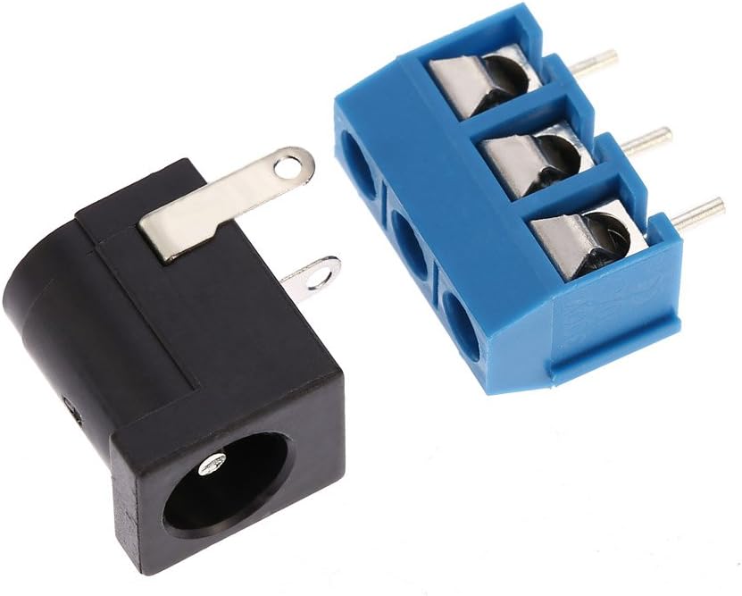
Image: A collection of loose electronic components, including resistors, capacitors, and jumpers, ready for assembly onto the PCB.
4. 조립 설명서
Follow these steps carefully to assemble your Weytoll XR2206 Signal Generator. A soldering iron, solder, and basic hand tools are required.
- PCB를 준비하세요: Inspect the Printed Circuit Board for any defects.
- Install Resistors and Capacitors: Solder the resistors and non-polarized capacitors onto the PCB according to their marked values and positions. Pay attention to the polarity of electrolytic capacitors.
- IC 소켓을 설치하세요: Solder the 16-pin IC socket onto the PCB. Ensure the notch on the socket aligns with the notch on the PCB silkscreen.
- Install Potentiometers: Solder the three potentiometers (Coarse, Fine, Amplitude) into their designated positions.
- Install Power Jack and Terminal Block: Solder the DC power jack and the 3-pin terminal block onto the PCB.
- Install XR2206 IC: Carefully insert the XR2206 IC into its socket, ensuring the notch on the IC aligns with the notch on the socket and PCB.
- Assemble Acrylic Case: Peel off the protective film from the acrylic case parts. Assemble the case around the completed PCB using the provided screws and nuts.
- 최종 확인: Before applying power, visually inspect all solder joints for shorts or cold joints. Ensure all components are correctly oriented.

Image: The bare red Printed Circuit Board (PCB) with component outlines and solder pads visible, ready for component placement.

Image: The XR2206 Integrated Circuit (IC) shown alongside its corresponding 16-pin socket, ready for installation.

Image: The DC power input jack and a blue 3-pin screw terminal block, used for power and signal output connections respectively.

Image: Various laser-cut acrylic pieces that form the protective enclosure for the signal generator, shown with their protective film.

Image: The fully assembled Weytoll XR2206 Signal Generator circuit board, showing all components soldered in place, including the XR2206 IC, potentiometers, and connectors.
5. 사용 설명서
This section details how to power on and operate your signal generator.
5.1 전원 켜기
- Connect a 9-12V DC power supply to the DC power jack. Alternatively, a 9V battery can be used (not included).
- Ensure connections are secure before applying power.
5.2 파형 선택
The kit supports sine, triangle, and square waveforms. Select the desired waveform using the jumpers on the PCB (J1, J2, etc., as marked for Sine/Triangle/Square).
5.3 주파수 조정
The frequency range is 1Hz to 1MHz. Use the "Coarse" potentiometer for broad frequency adjustments and the "Fine" potentiometer for precise tuning.
5.4 Amp광도 조정
Adjust the output signal amplitude using the "Amplitude" potentiometer.
5.5 출력 연결
Connect your testing equipment (e.g., oscilloscope, frequency counter) to the output terminals on the 3-pin terminal block (marked S/N/TR/SQU and GND).

Image: An oscilloscope screen showing examples of waveforms generated by the device, including 1KHz square wave, 1KHz sine wave, 1MHz square wave, triangle wave, and 50Hz sine wave.
6. 사양
| 특징 | 값 |
|---|---|
| 주파수 범위 | 1Hz - 1MHz |
| 파형 | Sine, Triangle, Square |
| 주파수 조정 | Coarse and Fine tuning |
| Amp광도 조정 | 조절할 수 있는 |
| 전원 공급 장치 | 9-12V DC external or 9V battery (not included) |
| 출력 임피던스 | 600 Ohm ± 10% (typical for XR2206 based circuits) |
| 모델 번호 | JZD7213503927391CH |
| 치수(조립됨) | Approx. 19.6 x 15.8 x 1.7 cm (based on package dimensions) |
| 무게(조립 시) | Approx. 70 grams (based on package weight) |
7. 유지관리
The Weytoll XR2206 Signal Generator requires minimal maintenance.
- 청소: 부드럽고 마른 천을 사용하여 기기 외부를 닦으세요. 액체 세척제나 용제는 사용하지 마세요.
- 저장: 사용하지 않을 때는 기기를 건조하고 먼지 없는 곳에 보관하십시오.
- 점검: Periodically check for loose connections or damaged components, especially if the device is frequently moved or used.
8. 문제 해결
If you encounter issues with your signal generator, refer to the following common problems and solutions.
| 문제 | 가능한 원인 | 해결책 |
|---|---|---|
| 출력 신호 없음 | No power, incorrect power supply, IC incorrectly inserted, soldering error. | 전원 연결 상태와 공급 전압을 확인하십시오.tage. Verify IC orientation and all solder joints. |
| Incorrect waveform | Incorrect jumper setting for waveform selection. | Adjust the waveform selection jumpers on the PCB. |
| 빈도 또는 amplitude not adjustable | Faulty potentiometer, soldering error on potentiometer connections. | Inspect potentiometer connections and test the potentiometer if possible. |
| 불안정한 출력 | Poor power supply filtering, cold solder joint, faulty component. | Ensure stable power supply. Re-check all solder joints. |
9. 보증 및 지원
As a DIY kit, specific warranty terms may vary. Please refer to the retailer or manufacturer's website for the most current warranty information and support options. For technical assistance, consult online forums or communities dedicated to the XR2206 function generator IC, as this is a widely documented component.