1. 서론
The Walfront Programmer Expansion Board is designed to facilitate the programming and bootloader burning of various microcontrollers, including Atmega 328P, Atmega 168P, and Atmega 8. This board serves as an essential tool for developers and hobbyists working with Arduino-compatible platforms such as Arduino, Nano, and Pro Mini (5V 16M). It integrates key features like LED indicators, a buzzer, and multiple programming interfaces to streamline the development process.
2. 특징
- LED 표시등: Onboard LEDs provide visual feedback. A "breathing light" indicates normal power, a flashing PROG light signifies active programming, and a red ERROR light indicates programming failure.
- 28-Pin ZIF Socket: Features a 28P lock seat for convenient burning of bootstrap programs onto Atmega 328P, Atmega 168P, and Atmega 8 microcontrollers.
- ISP Interfaces: Includes ISP_6PIN and ISP_10PIN interfaces for external board bootloader burning.
- USB to TTL Programmer Interface: Equipped with FT232RL and CH340G interfaces for uploading code to chips placed in the 28P lock seat.
- Onboard Buzzer: Provides audible feedback for programming status. A successful bootloader burn is indicated by two beeps.
- 호환성: Supports programming for Arduino, Nano, and Pro Mini (5V 16M) boards.
3. 사양
| 매개변수 | 값 |
|---|---|
| 운영 볼륨tage | 5V |
| Working Current (Maximum) | 500mA |
| Supported Microcontrollers | Atmega 328P, Atmega 168P, Atmega 8 |
| Supported Boards | Arduino, Nano, Pro Mini (5V 16M) |
| 인터페이스 | 28P ZIF Socket, ISP_6PIN, ISP_10PIN, FT232RL, CH340G USB to TTL |
| 모델 번호 | Walfrontyz6uo8t01h |
| 품목 무게 | 0.03 킬로그램 |
4. 설정
Before using the Walfront Programmer Expansion Board, ensure you have the necessary drivers installed for the FT232RL or CH340G USB to TTL converter, if you plan to use that functionality.
- 호스트에 연결: Connect the programmer expansion board to your computer using a standard USB cable. The board will draw power from the USB connection.
- Observe Power Indicator: Upon connection, the onboard LED indicator should light up, often with a "breathing light" effect, indicating normal power supply.
- 드라이버 설치(필요한 경우): If your operating system does not automatically recognize the USB to TTL converter, you may need to manually install drivers for FT232RL or CH340G. These drivers are typically available from the chip manufacturer's website or common microcontroller development resources.
- Prepare Microcontroller (for ZIF socket): If burning a bootloader to a bare microcontroller (e.g., Atmega 328P), carefully insert the chip into the 28-pin ZIF (Zero Insertion Force) socket. Ensure correct orientation, aligning pin 1 of the chip with the corresponding mark on the socket. Close the ZIF socket lever to secure the chip.
- Prepare External Board (for ISP): If burning a bootloader to an external board (e.g., Arduino Nano), connect the ISP_6PIN or ISP_10PIN interface on the expansion board to the corresponding ISP header on your target board using an appropriate cable.

그림 1: 상단 view of the Walfront Programmer Expansion Board, showing the 28-pin ZIF socket, ISP headers, and LED indicators.
5. 사용 설명서
5.1. Burning Bootloader to Microcontroller in ZIF Socket
- Insert Chip: Carefully insert the target microcontroller (e.g., Atmega 328P) into the 28-pin ZIF socket, ensuring correct orientation.
- 컴퓨터에 연결: Connect the expansion board to your computer via USB.
- 소프트웨어 구성 : Open your preferred IDE (e.g., Arduino IDE). Select the appropriate board type (e.g., "Arduino Uno" for Atmega328P) and the correct COM port for the expansion board's USB to TTL interface.
- Select Programmer: Go to "Tools" > "Programmer" and select "Arduino as ISP" or a compatible programmer option.
- Burn Bootloader: Go to "Tools" > "Burn Bootloader".
- 모니터 표시기:
- The PROG LED will flash during the burning process.
- Upon successful completion, the onboard buzzer will emit two beeps.
- If the ERROR LED (red) illuminates, the burning process has failed.
- Remove Chip: After successful burning, open the ZIF socket lever and carefully remove the microcontroller.
5.2. Burning Bootloader to External Board via ISP
- Connect ISP: Connect the ISP_6PIN or ISP_10PIN header on the expansion board to the ISP header on your target board (e.g., Arduino Nano).
- 컴퓨터에 연결: Connect the expansion board to your computer via USB. Ensure the target board is also powered, if required.
- 소프트웨어 구성 : In your IDE, select the target board type and the correct COM port for the expansion board.
- Select Programmer: Go to "Tools" > "Programmer" and select "Arduino as ISP" or a compatible programmer option.
- Burn Bootloader: Go to "Tools" > "Burn Bootloader".
- 모니터 표시기: Observe the PROG and ERROR LEDs, and listen for the buzzer as described in section 5.1.
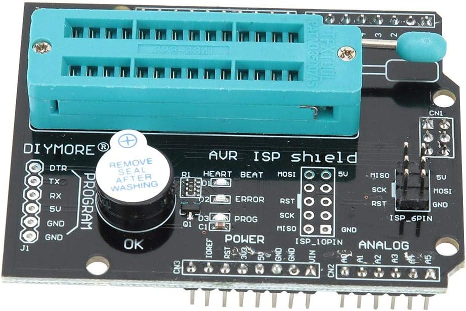
그림 2: 세부사항 view of the 28-pin ZIF socket, LED indicators (Heart Beat, Error, Prog), and the onboard buzzer.
6. 유지관리
The Walfront Programmer Expansion Board is designed for durability and requires minimal maintenance.
- 청소: Keep the board clean and free from dust and debris. Use a soft, dry cloth for cleaning. Avoid using liquids or abrasive cleaners.
- 저장: Store the board in a dry, static-free environment when not in use.
- 손질: Handle the board by its edges to avoid touching sensitive components, especially the ZIF socket pins.
- ZIF Socket Care: When inserting or removing chips, always ensure the ZIF socket lever is fully open to prevent damage to the chip pins or the socket itself.

그림 3: 하단 view of the Walfront Programmer Expansion Board, illustrating the solder points and circuit traces.
7. 문제 해결
- 컴퓨터가 보드를 인식하지 못합니다:
- USB 케이블이 제대로 연결되어 있는지 확인하세요.
- Verify that the necessary FT232RL or CH340G drivers are correctly installed. Check Device Manager on Windows or
lsusbon Linux for device recognition. - 다른 USB 포트나 케이블을 사용해 보세요.
- ERROR LED Illuminates During Programming:
- Incorrect Chip Insertion: For ZIF socket programming, ensure the microcontroller is inserted correctly and the ZIF lever is fully closed. Verify pin 1 alignment.
- Incorrect Wiring (ISP): For ISP programming, double-check all connections between the expansion board and the target board. Ensure MISO, MOSI, SCK, RST, VCC, and GND lines are correctly connected.
- Incorrect Board/Programmer Selection: In your IDE, confirm that the correct board type and programmer (e.g., "Arduino as ISP") are selected.
- Faulty Chip: The target microcontroller might be faulty. Try with a different chip if available.
- 전원 문제: Ensure adequate power supply to both the expansion board and the target board (if external).
- No Buzzer Sound After Programming:
- If the ERROR LED is off but no two beeps are heard, the programming might still have failed silently, or the buzzer itself could be faulty. Refer to the ERROR LED for primary failure indication.
- Re-attempt the programming process.
8. 보증 및 지원
Specific warranty information for the Walfront Programmer Expansion Board (Model: Walfrontyz6uo8t01h) is not provided in the product details. For warranty claims or technical support, please refer to the retailer or manufacturer's official support channels.
당신은 방문할 수 있습니다 Walfront Store on Amazon 제품에 대한 추가 정보를 원하시거나 판매자에게 문의하려면 여기를 클릭하십시오.