
1. 제품 오버view
The Riello MG569 BWZG is a sophisticated control unit designed for reliable and efficient operation of Riello gas burners. This unit manages the ignition, flame supervision, and safety functions of the burner, ensuring optimal performance and adherence to safety standards. It is a direct replacement for several older models, offering enhanced functionality and compatibility.
1.1 호환성
This control unit is compatible with the following Riello burner series:
- BS1-911T1, BS1D-915T1
- BS2-912T1, BS2D-916T1
- BS3-913T1, BS3D-917T1
- BS4-914T1, BS4D-918T1
It also replaces previous control unit models including 3002949, 3002967, 569SE, 568SE, 566SE rev3, 566SE rev2, 566SE rev1, and 525SE/G.
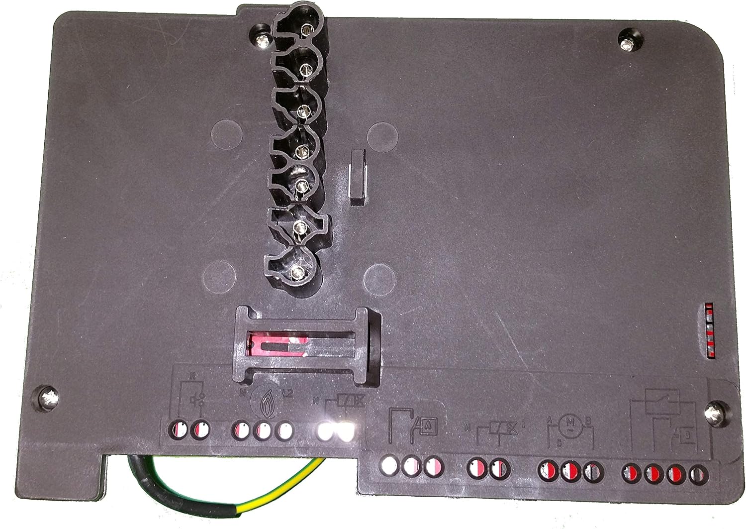
그림 1: 상단 view of the Riello MG569 BWZG Control Unit, illustrating the various terminal connections for power, ignition, and burner components.
2. 설정 및 설치
Installation of the Riello MG569 BWZG control unit requires specialized knowledge of electrical systems and burner operation. It is strongly recommended that installation be performed by a qualified and certified technician to ensure safety and proper functionality.
2.1 안전 예방 조치
- 전원 분리: Always ensure the main power supply to the burner system is disconnected before beginning any installation or maintenance work.
- 호환성 확인: Confirm that the MG569 BWZG unit is the correct replacement or component for your specific Riello burner model.
- Follow Wiring Diagrams: Refer to the specific wiring diagrams provided with your burner system and the control unit for accurate connections. Incorrect wiring can lead to damage or hazardous conditions.
- 환경 조건: Install the unit in a dry, protected environment, away from excessive heat, moisture, or corrosive substances.
2.2 설치 단계(일반)
- 오래된 장치 제거: Carefully disconnect and remove the existing control unit, noting all wiring connections.
- 새로운 유닛 장착: Securely mount the Riello MG569 BWZG control unit in the designated position.
- 배선 연결: Connect all electrical wires according to the burner's wiring diagram. This typically includes connections for power supply (L1, N), ignition transformer, flame sensor, motor, and fuel valve. Ensure all connections are tight and secure.
- 접지: Verify that the unit and burner system are properly grounded to prevent electrical hazards.
- 초기 점검: Before restoring power, double-check all connections for correctness and security.
- 복원력 : Carefully restore power to the burner system.
- 테스트 작업: Initiate a test firing sequence to ensure the burner ignites and operates correctly, and that all safety features are functioning.

그림 2: 또 다른 view of the Riello MG569 BWZG Control Unit, highlighting the terminal block for electrical connections and mounting screw locations.
3. 사용 설명서
The Riello MG569 BWZG control unit operates automatically once installed and powered. Its primary function is to manage the burner's ignition sequence, flame supervision, and shutdown procedures in case of malfunction.
3.1 Normal Operation Sequence
- 시작: Upon receiving a call for heat, the control unit initiates a pre-purge cycle to clear the combustion chamber.
- 점화: After pre-purge, the ignition transformer is activated, creating a spark, and the fuel valve opens to allow fuel into the combustion chamber.
- 화염 감지: The flame sensor (e.g., photocell or ionization probe) detects the presence of a flame. If a flame is established within the safety time, the ignition spark is cut off, and the burner continues to operate.
- 달리기: The burner operates under the supervision of the control unit, which continuously monitors the flame.
- 일시 휴업: When the call for heat ends, the fuel valve closes, and the burner shuts down. A post-purge cycle may follow.
3.2개의 표시등
The control unit may feature indicator lights (LEDs) to signal its operational status or fault conditions. Consult your burner's specific documentation for a detailed explanation of these indicators. Typically, a steady green light indicates normal operation, while a flashing or red light signifies a fault.
4. 유지관리
Regular maintenance is crucial for the longevity and safe operation of your burner system and its control unit. All maintenance should be performed by a qualified service technician.
4.1 권장 유지보수 일정
- 연례 검사: Have a qualified technician inspect the entire burner system, including the control unit, flame sensor, ignition electrodes, and fuel lines, at least once a year.
- 청소: Ensure the control unit and its connections are free from dust, dirt, and moisture. Do not use abrasive cleaners or solvents.
- 연결 확인: Periodically, a technician should verify that all electrical connections to the control unit are secure and free from corrosion.
메모: The control unit itself is a sealed component and is not user-serviceable. Any internal issues require replacement of the unit.
5. 문제 해결
This section provides general guidance for common issues. For detailed diagnostics, consult a qualified technician.
| 문제 | 가능한 원인 | 행동 |
|---|---|---|
| Burner does not start / No ignition |
|
|
| Burner ignites but immediately shuts down (flame failure) |
|
|
| Control unit shows a fault code/light |
|
|
6. 기술 사양

그림 3: 측면 view of the Riello MG569 BWZG Control Unit, displaying the product label with key technical specifications.
| 특징 | 세부 사항 |
|---|---|
| 모델 번호 | MG569 BWZG |
| 제조업체 | 리엘로 |
| 권tage | 210-230V ~ 50/60Hz |
| 퓨즈 | T4A 250V~ |
| 점화 Voltage | 18kVpk |
| 현재의 | 11mArms |
| 한국어: | 748810822879 |
| 호환성 | Riello BS1, BS2, BS3D, BS4D series burners |
| 모델을 교체합니다 | 3002949, 3002967, 569SE, 568SE, 566SE rev3, 566SE rev2, 566SE rev1, 525SE/G |
7. 보증 정보
Specific warranty terms for the Riello MG569 BWZG control unit are typically provided by the seller or manufacturer at the time of purchase. Please retain your proof of purchase for warranty claims.
Information regarding the availability of spare parts is currently unavailable. For any spare part inquiries, please contact your supplier or an authorized Riello service center.
8. 고객 지원
For technical assistance, service, or further information regarding the Riello MG569 BWZG control unit, please contact:
- Your authorized Riello dealer or installer.
- An authorized Riello service center.
- The manufacturer directly via their official web사이트 또는 연락처 채널.
When contacting support, please have your product model number (MG569 BWZG) and any relevant purchase details ready.