1. 서론
This manual provides detailed instructions for installing, configuring, and maintaining your GIGABYTE GA-B150M-D3H Micro ATX motherboard. The GA-B150M-D3H is designed to support 6th Generation Intel Core Processors and features Dual Channel DDR4 memory, PCIe Gen3 x4 M.2 connector, SATA Express, and 8-channel HD audio with Audio Noise Guard.
Please read this manual thoroughly before beginning installation to ensure proper setup and operation.
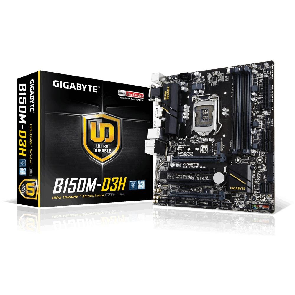
Image 1.1: GIGABYTE GA-B150M-D3H Micro ATX Motherboard. This image displays the overall layout of the motherboard, highlighting its compact Micro ATX form factor and various component slots.
2. 안전 정보
메인보드 손상 및 부상을 방지하기 위해 다음 안전 수칙을 준수하십시오.
- 제품을 만지기 전에 항상 전원 코드를 벽면 콘센트에서 분리하십시오.
- 정전기 방지 손목 끈을 착용하거나 접지된 금속 물체를 자주 만져 정전기를 방전시키세요.
- 민감한 부품을 만지지 않도록 마더보드의 가장자리를 잡으세요.
- 마더보드를 습기와 극한 온도에 두지 마세요.
- 과열을 방지하려면 컴퓨터 케이스 내부의 적절한 환기를 확보하세요.
3. 패키지 내용
마더보드 패키지에 모든 품목이 들어 있는지 확인하세요.
- GIGABYTE GA-B150M-D3H Motherboard
- 사용자 설명서
- I / O 실드
- SATA 케이블
- 드라이버 CD/DVD
Note: Contents may vary slightly depending on region or revision.
4. 마더보드 레이아웃
Familiarize yourself with the various components and connectors on the GA-B150M-D3H motherboard.
Image 4.1: GIGABYTE GA-B150M-D3H Motherboard Layout. This image provides a visual reference for the location of key components such as the CPU socket, DIMM slots, PCIe slots, SATA ports, and M.2 connector.
주요 구성 요소:
- LGA 1151 CPU 소켓: For 6th Generation Intel Core Processors.
- DDR4 DIMM Slots (4): Supports Dual Channel DDR4 memory up to 2133 MHz.
- PCIe 슬롯: Includes PCIe Gen3 x16 for graphics cards and PCIe x1 slots for expansion.
- M.2 커넥터: Supports PCIe NVMe & SATA SSDs with up to 32Gb/s data transfer.
- SATA Express Connector: For up to 16Gb/s data transfer.
- SATA 6Gb/s 포트: For connecting traditional SATA storage devices.
- 24핀 ATX 전원 커넥터: 주전원 입력.
- 8-Pin ATX 12V Power Connector: CPU power input.
- 전면 패널 헤더: For power button, reset button, LED indicators, and USB ports.
- 오디오 커넥터: 8-channel HD Audio with high quality capacitors and Audio Noise Guard.
5. 설정 및 설치
마더보드와 구성 요소를 올바르게 설치하려면 다음 단계를 따르세요.
5.1. CPU 설치
- Locate the LGA 1151 CPU socket.
- CPU 소켓 레버를 열고 로드 플레이트를 들어 올립니다.
- CPU의 금색 삼각형이 소켓의 삼각형과 일치하는지 확인하여 CPU를 소켓에 조심스럽게 맞춰 끼우십시오. CPU를 소켓에 억지로 끼워 넣지 마십시오.
- 적재판을 내리고 레버로 고정하십시오.
5.2. CPU 쿨러 설치
Refer to your CPU cooler's instruction manual for specific installation steps. Ensure thermal paste is applied correctly between the CPU and cooler base.
5.3. 메모리(RAM) 설치
- DDR4 DIMM 슬롯의 양쪽 끝에 있는 클립을 엽니다.
- 메모리 모듈을 슬롯에 맞춰서 모듈의 홈이 슬롯의 키와 일치하는지 확인합니다.
- 클립이 제자리에 고정될 때까지 메모리 모듈의 양쪽 끝을 단단히 누릅니다.
- For dual-channel performance, install memory modules in matching colored slots (e.g., DIMM1 and DIMM2).
5.4. 확장 카드 설치
- Remove the metal bracket from the desired PCIe slot on your computer case.
- 확장 카드를 PCIe 슬롯에 맞춰 정렬하고 제대로 장착될 때까지 단단히 누르십시오.
- 카드(그래픽 카드)를 나사로 컴퓨터 케이스에 고정하세요.
5.5. 저장 장치 연결
- SATA 장치: Connect one end of the SATA data cable to a SATA 6Gb/s port on the motherboard and the other end to your hard drive or SSD. Connect the SATA power cable from your power supply to the device.
- M.2 SSD: M.2 SSD를 M.2 슬롯에 비스듬히 삽입한 다음, 부드럽게 아래로 눌러 제공된 나사로 고정하십시오.
- SATA Express: If using a SATA Express device, connect it to the designated SATA Express connector.
5.6. 전면 패널 커넥터 연결
Connect the cables from your computer case's front panel (power button, reset button, HDD LED, power LED, front USB, front audio) to the corresponding headers on the motherboard. Refer to the motherboard layout diagram for exact locations and pin assignments.
5.7. 전원 공급 장치 연결
- 파워서플라이의 24핀 ATX 메인 전원 커넥터를 마더보드의 24핀 전원 소켓에 연결하십시오.
- Connect the 8-pin ATX 12V CPU power connector to the 8-pin socket near the CPU.
- 모든 전원 연결이 단단히 고정되었는지 확인하십시오.
6. 사용 설명서
6.1. 첫 번째 부팅
After assembling all components, connect your monitor, keyboard, and mouse. Power on the system. The system should display the GIGABYTE splash screen and then enter the BIOS/UEFI setup or attempt to boot from a connected storage device.
6.2. BIOS/UEFI 설정
BIOS/UEFI 설정으로 들어가려면 다음 버튼을 누르십시오. 델 key repeatedly during the boot process when the GIGABYTE logo appears. Here you can configure system settings, boot order, and monitor hardware status. The GA-B150M-D3H features GIGABYTE UEFI Dual BIOS for enhanced reliability.
6.3. 드라이버 설치
After installing your operating system, install the necessary drivers for the motherboard components. These can be found on the included driver CD/DVD or downloaded from the official GIGABYTE website. Key drivers include chipset, audio (Realtek ALC892 codec), LAN, and any integrated graphics drivers.
6.4. 운영체제 설치
Insert your operating system installation media (USB drive or DVD) and configure the boot order in the BIOS/UEFI to boot from it. Follow the on-screen instructions to install your preferred operating system (e.g., Windows 8.1, Windows 10).
7. 유지관리
7.1. 청소
컴퓨터 케이스 내부를 정기적으로 청소하여 먼지 축적을 방지하고 과열을 예방하세요. 팬, 방열판 및 마더보드 부품의 먼지는 압축 공기를 사용하여 제거하십시오. 청소하기 전에 시스템 전원을 끄고 전원 케이블을 뽑으십시오.
7.2. BIOS 업데이트
GIGABYTE periodically releases BIOS updates to improve system stability, compatibility, and performance. Visit the official GIGABYTE website for your motherboard model (GA-B150M-D3H) to check for the latest BIOS version and follow the provided instructions for updating. Exercise caution during BIOS updates, as an interruption can render the motherboard inoperable.
8. 문제 해결
이 섹션에서는 일반적으로 발생할 수 있는 문제에 대해 설명합니다.
8.1. 전원이 켜지지 않음 / 시스템이 켜지지 않음
- Check if the power supply is connected correctly to the motherboard (24-pin and 8-pin connectors).
- 전원 스위치가 켜짐 위치에 있는지 확인하십시오.
- 전면 패널 전원 버튼 케이블이 마더보드 헤더에 올바르게 연결되어 있는지 확인하세요.
- 다른 시스템이나 전원 공급 장치 테스터를 사용하여 전원 공급 장치를 테스트하십시오.
8.2. 디스플레이 출력 없음
- Ensure the monitor is connected to the correct graphics output (either integrated graphics on the motherboard or a dedicated graphics card).
- 그래픽 카드와 메모리 모듈을 다시 장착하세요.
- 메모리 모듈을 하나만 설치한 상태로 부팅해 보세요.
- 모니터의 전원이 켜져 있고 올바른 입력 소스로 설정되어 있는지 확인하세요.
8.3. 시스템 불안정성/충돌
- CPU와 GPU 온도가 안전 작동 범위 내에 있는지 확인하십시오.
- Verify that all drivers are installed and up to date.
- 메모리 진단 도구를 실행하여 RAM에 오류가 있는지 확인하십시오.
- Ensure the power supply provides sufficient and stable power to all components.
9. 사양
Detailed technical specifications for the GIGABYTE GA-B150M-D3H motherboard:
| 특징 | 사양 |
|---|---|
| 모델명 | GA-B150M-D3H |
| 폼 팩터 | 마이크로 ATX(24.4cm x 22.5cm) |
| CPU 소켓 | LGA 1151 |
| 호환 프로세서 | 6세대 인텔 코어 프로세서 |
| 칩셋 | 인텔 B150 익스프레스 칩셋 |
| 메모리 기술 | DDR4 |
| 메모리 슬롯 | 4 x DDR4 DIMM sockets (Dual Channel) |
| 최대 메모리 용량 | 16GB (XNUMX기가바이트) |
| 메모리 클럭 속도 | 2133MHz |
| PCIe 슬롯 | 1 x PCI Express x16, 1 x Total PCIe Ports |
| 스토리지 인터페이스 | PCIe Gen3 x4 M.2, SATA Express, SATA 6Gb/s |
| 오디오 코덱 | Realtek ALC892 codec, 8-channel HD Audio |
| USB 포트 | Total 8 USB Ports (including USB 2.0) |
| 주전원 커넥터 | 24핀 ATX |
| CPU 전원 커넥터 | 8-Pin ATX 12V |
| 독특한 특징 | GIGABYTE UEFI Dual BIOS, Audio Noise Guard with LED Trace Path Lighting, App Center (Easy Tune, Cloud Station) |
10. 보증 및 지원
For warranty information, please refer to the warranty card included in your product package or visit the official GIGABYTE web사이트. 보증 약관은 지역에 따라 다를 수 있습니다.
For technical support, driver downloads, BIOS updates, and further product information, please visit the GIGABYTE official support web대지:
https://www.gigabyte.com/Support
When contacting support, please have your motherboard model (GA-B150M-D3H) and serial number ready.


