
1. 서론
This manual provides instructions for the installation, operation, maintenance, and troubleshooting of the Juniper EX3200-24T Layer 3 Switch. The EX3200-24T is a fixed-configuration switch designed for access-layer deployments in various network environments, offering comprehensive Layer 2 and Layer 3 switching capabilities.
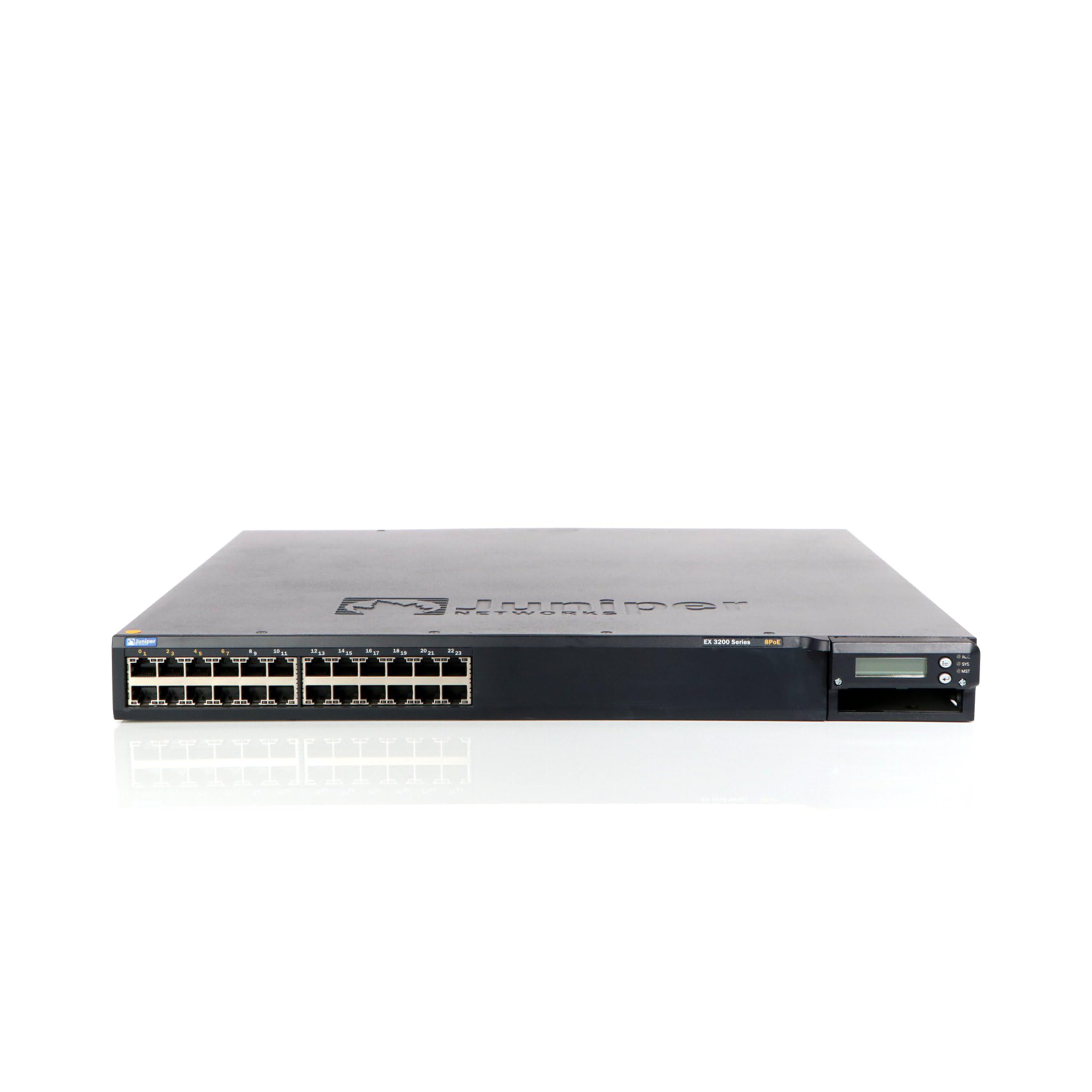
그림 1: 전면 view of the Juniper EX3200-24T Layer 3 Switch. This image displays the 24 Ethernet ports, along with various status indicator lights and the Juniper Networks branding.
2. 설정
Follow these steps to properly set up your Juniper EX3200-24T switch.
2.1 풀기 및 검사
- 스위치를 포장에서 조심스럽게 꺼내세요.
- Inspect the switch for any signs of physical damage. If damage is found, contact your vendor immediately.
- 포장 목록에 기재된 모든 구성품이 있는지 확인하십시오.
2.2 랙 마운팅(선택 사항)
The EX3200-24T can be mounted in a standard 19-inch equipment rack. Use the provided rack-mount kit and follow the instructions included with the kit for secure installation.
2.3 전원 연결
- Ensure the power switch on the rear panel of the switch is in the OFF position.
- Connect the provided AC power cord to the power inlet on the rear of the switch.
- 전원 코드의 다른 쪽 끝을 접지된 전기 콘센트에 꽂습니다.
2.4 네트워크 케이블 연결
Connect Ethernet cables from your network devices (computers, servers, other switches) to the 10/100/1000Base-T ports on the front panel of the EX3200-24T switch. Ensure cables are securely seated.
3. 사용 설명서
This section outlines the basic operation of the Juniper EX3200-24T switch.
3.1 스위치 전원 켜기
After connecting the power cord, flip the power switch on the rear panel to the ON position. The system status LEDs on the front panel will illuminate during the boot process.
3.2 Understanding Status LEDs
The front panel features various LEDs to indicate the operational status of the switch and its ports:
- 시스템 LED: Indicates system status (e.g., green for normal operation, amber for warning, red for critical error).
- ALM LED: 알람 상태를 나타냅니다.
- PPM LED: Indicates power supply module status.
- 포트 LED: Each port has LEDs indicating link status and activity (e.g., green for link, blinking green for activity).
3.3 초기 구성 (콘솔 접속)
초기 설정을 위해 관리 워크스테이션에서 스위치의 콘솔 포트로 콘솔 케이블(RJ-45-DB-9)을 연결하십시오. 다음 설정으로 터미널 에뮬레이션 프로그램(예: PuTTY, Tera Term)을 사용하십시오.
- 전송 속도 : 9600
- 데이터 비트: 8
- 패리티: 없음
- 정지 비트: 1
- 흐름 제어: 없음
Refer to the Juniper Networks documentation for detailed configuration procedures.
4. 유지관리
Regular maintenance ensures optimal performance and longevity of your EX3200-24T switch.
4.1 청소
- 스위치 외부를 주기적으로 부드럽고 마른 보풀 없는 천으로 닦아주세요.
- Ensure ventilation openings are free from dust and obstructions to prevent overheating. Do not use liquid or aerosol cleaners directly on the switch.
4.2 펌웨어 업데이트
Juniper Networks periodically releases firmware updates to improve performance, add features, and address security vulnerabilities. It is recommended to keep the switch firmware updated. Refer to the official Juniper Networks support website for the latest firmware and update procedures.
4.3 환경 고려 사항
Operate the switch within its specified environmental limits (temperature, humidity) to prevent damage and ensure reliable operation. Avoid exposing the switch to direct sunlight, excessive heat, or moisture.
5. 문제 해결
This section provides solutions to common issues you might encounter with your EX3200-24T switch.
5.1 전원 없음
- 징후: No LEDs are illuminated, and the switch does not power on.
- 행동:
- 전원 코드가 스위치와 전기 콘센트에 모두 안전하게 연결되어 있는지 확인하세요.
- 후면 패널의 전원 스위치가 ON 위치에 있는지 확인하세요.
- Check the electrical outlet with another device to confirm it is functional.
- 전원 스트립이나 UPS를 사용하는 경우 전원이 켜져 있고 제대로 작동하는지 확인하세요.
5.2 네트워크 연결 없음
- 징후: Devices connected to the switch cannot access the network.
- 행동:
- Check the port LEDs on the switch for the connected device. A solid green LED indicates a link. If no link, try a different port or cable.
- Verify the network cable is securely connected at both ends (switch and device).
- 연결된 장치의 네트워크 어댑터가 활성화되어 있고 올바르게 구성되어 있는지 확인하십시오.
- If multiple devices are affected, check the uplink connection from the EX3200-24T to your core network.
- Consult the switch's configuration for VLANs, IP addressing, and other network settings.
5.3 System Alarm LED (ALM) is Amber/Red
- 징후: The ALM LED is illuminated amber or red.
- 행동:
- Log in to the switch via the console or network management interface.
- Check system logs and alarm messages for details on the specific issue.
- Common causes include power supply issues, fan failures, or high temperature.
- Address the root cause as indicated by the logs.
6. 사양
Key technical specifications for the Juniper EX3200-24T Layer 3 Switch:
| 특징 | 사양 |
|---|---|
| 상표 | 주니퍼 네트웍스 |
| 모델 번호 | EX3200-24T |
| 포트 수 | 24 (16 x 10/100/1000Base-T, 8 x 10/100/1000Base-T) |
| 확장 슬롯 | 1 x Expansion Slot |
| 데이터 전송 속도 | 초당 1기가비트 |
| 레이어 지원 | 3층 |
| 품목 무게 | 14.9 파운드 |
| 색상 | 검은색 |
| 호환 장치 | 데스크탑 |
| 한국어: | 832938037793 |
7. 보증 및 지원
7.1 제품 보증
The Juniper EX3200-24T Layer 3 Switch is covered by a standard manufacturer's warranty. For detailed information regarding warranty terms, duration, and coverage, please refer to the warranty card included with your product or visit the official Juniper Networks web대지.
7.2 기술 지원
For technical assistance, troubleshooting beyond this manual, or to report issues, please contact Juniper Networks technical support. Support resources, including documentation, FAQs, and contact information, are available on the official Juniper Networks support portal: